

Description
- Brand: Honeywell
- Full Model Number: 51309355-501
- Lifecycle Status: Obsolete / Replaced by later DR4500A Truline main-board variants
- Core Function: DR4500 circular chart recorder main PCB
- Top 3 Technical Specs: Main processor/control PCB; DR4500 chart-recorder platform; 0–55°C ambient operating range
- Stock & Condition: New Surplus / Tested Refurbished / Fast Dispatch subject to physical stock confirmation
Honeywell’s DR4500A documentation lists 51309355-501 as the Main PCB for the earlier DR4500 recorder configuration. Later DR4500A Truline documentation lists different main-board part numbers by recorder model, indicating that the board configuration is model-specific.
Module 3: Obsolescence & Supply Chain Deep Dive
When an installed Honeywell DR4500 loses its main processor board, the recorder can become economically unserviceable even though the transformer, input boards, chart mechanism, enclosure, and other assemblies remain usable. That is where 51309355-501 matters: Honeywell’s parts documentation identifies it as the Main PCB in the DR4500 recorder assembly. The sourcing challenge is the age of the platform. Current spare-parts references classify this exact board as obsolete or no longer routinely available, while other references still show it as a sought-after replacement part. For a plant with an operating legacy recorder, obtaining a verified board can therefore be much faster than engineering a complete replacement recorder into an existing panel.
The TCO case depends on preserving the existing recorder hardware. A board-level replacement can retain installed input PCBs, chart-drive mechanics, enclosure, wiring, and configured options, avoiding a broader retrofit and the associated engineering, panel work, drawing revision, and commissioning costs. Honeywell’s older DR4500 parts list explicitly identifies 51309355-501 as a recommended spare, with one spare recommended per ten recorders in the basic configuration. That historical spare strategy is useful context today: for a remaining installed base, a tested legacy board can have value far beyond its component cost because it protects against an otherwise difficult recorder-level failure.
Module 4: Compatibility & Replacement Matrix
| Engineering Check | Assessment for 51309355-501 |
|---|---|
| Replacement Classification | Drop-in Replacement for the matching legacy configuration |
| Software Compatibility | Configuration-dependent; no generic firmware claim should be made |
| Hardware Modification | Normally not required for a direct same-part replacement |
| System | Honeywell / Classic Series Circular Chart Recorder |
| Board Type | Main PCB / Main Processor Board |
| Primary Role | Central recorder control and processing |
| Ambient Temperature Reference | 0°C to 55°C |
| Typical Replacement Time | 2–4 hours, depending on recorder options and access |
| Commissioning Requirement | Power-up verification, input-channel test, recorder operation check, option verification, calibration review |
| Upgrade Alternative | Evaluate later DR4500A Truline board variants or a recorder migration only after exact model identification |
The key issue is model-specific board configuration. Later Honeywell DR4500A Truline documentation identifies 51309355-502, -503, -504, and -505 as main PCB variants for different recorder models, while the older documentation identifies 51309355-501 as the basic main PCB.
⚠️ Field Traps — Watch Out
Recorder model mismatch: Do not approve a replacement solely from the “” family name. Later documentation associates different main PCB part numbers with specific DR45AT, DR45AR, DR45AW, and DR45AH/AP/AS configurations. The exact recorder model and revision must be checked before substitution.
Processor-board revision: Honeywell’s documentation notes a processor-board change in approximately September 2009 for later configurations. A newer or different main-board revision may not be a direct substitute for an older assembly without confirming the recorder’s model, daughterboard arrangement, and option set.
Option-board dependency: configurations can include alarm/digital-input boards, control-output boards, RS485 communications, and auxiliary outputs. Confirm these options before transferring or replacing the main PCB so that the installed configuration remains supported.
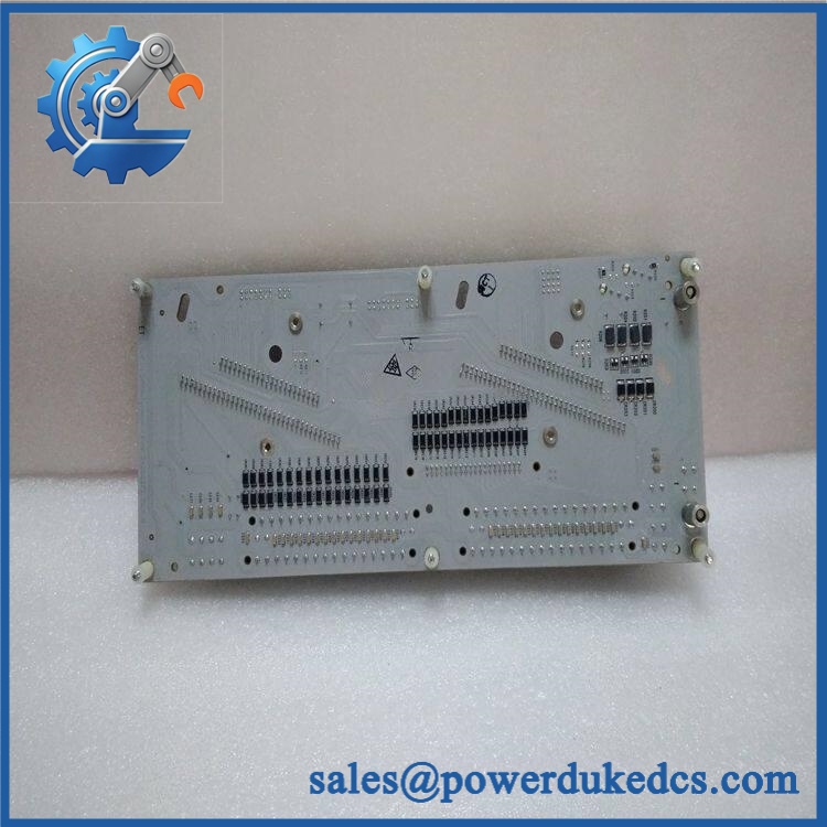
Honeywell 51309355-501
Module 5: Quality Assurance & Testing SOP
For 51309355-501, visual inspection alone is insufficient. The board should be evaluated as the controller of a complete recorder.
1. OEM anti-counterfeit visual inspection
Verify Honeywell markings, exact 51309355-501 identification, PCB revision markings, connector locations, processor devices, memory devices, daughterboard interfaces, and board construction. Photograph the complete board and all labels.
2. PCB condition inspection
Inspect capacitors, ICs, connectors, solder joints, terminals, battery area, transformers or power-interface components, and PCB traces. Check for corrosion, contamination, heat discoloration, cracked solder joints, damaged components, and unauthorized rework.
3. Power-rail verification
Before full installation, check relevant board power-input and distribution paths for shorts or abnormal resistance. Apply controlled power through a current-limited test setup and monitor startup behavior.
4. Power-on self-test (POST)
Install the board in a compatible test assembly. Verify normal initialization, display/control response, chart-recorder control behavior, and absence of abnormal fault indications.
5. Input-board communication test
Connect compatible input PCBs and confirm that the main PCB correctly recognizes and processes representative input signals. The architecture can use multiple input PCB positions depending on configuration.
6. Recorder mechanism test
Operate the chart-recorder mechanism through controlled test cycles. Confirm that the main PCB can command the relevant recorder functions without intermittent operation or unexpected resets.
7. Option verification
Where the unit is configured for alarm/digital inputs, control outputs, RS485 communication, or auxiliary outputs, test the corresponding interfaces against the installed configuration. Honeywell’s parts documentation identifies these assemblies as optional components.
8. Calibration and signal verification
Apply known test signals through the appropriate input assembly and compare displayed/recorded values against calibrated reference values. Verify that the recorder maintains stable operation over an extended test period.
9. Thermal soak
Operate the assembled recorder under representative load for an extended period while monitoring supply behavior and board temperature. The commonly published ambient operating range for the board/recorder configuration is 0°C to 55°C.
10. Final QC record
Document part number, PCB revision, serial/traceability information where available, test setup, measured values, option configuration, test duration, photographs, and final QC status.
Module 6: Procurement & Lifecycle FAQ
Is 51309355-501 genuinely in stock, and what is the cutoff for emergency shipping?
Do not treat online availability indicators as confirmation of physical inventory. Current sources show conflicting availability conditions: some listings show the part available, while others classify it as obsolete or unavailable. For an emergency requirement, confirm the exact quantity, board revision, condition, test status, and same-day dispatch cutoff before releasing the PO.
How do you guarantee the condition and authenticity of an obsolete or surplus 51309355-501?
The unit should be verified against the exact Honeywell part number, inspected at PCB level, powered through a controlled test fixture, installed in a compatible assembly, and tested with representative input and recorder functions. A documented QC report with board photographs provides a much stronger acceptance basis than a visual inspection alone.
Are there firmware compatibility issues I should warn my engineers about before issuing the PO?
The larger risk is hardware configuration compatibility, not a simple firmware-flash requirement. Honeywell documentation distinguishes main-board part numbers by /DR4500A recorder model and configuration. Engineers should confirm the exact recorder model, main-board revision, daughterboard arrangement, input-board count, communications options, and installed control-output options.
Can 51309355-501 be replaced by 51309355-502?
Do not assume direct interchangeability. Honeywell documentation identifies 51309355-501 as the main PCB in the earlier documentation, whereas 51309355-502 and subsequent variants appear in later Truline configurations and are assigned according to specific recorder models. An engineering comparison of the complete recorder configuration is required before approving a substitute.
What warranty and return terms should procurement require?
For obsolete or surplus boards, require written warranty coverage for the specific tested 51309355-501, including DOA terms, return authorization, inspection period, and the remedy for a board that fails during incoming inspection or controlled commissioning. The commercial documentation should also state whether the supplied board is new surplus, refurbished, repaired, or previously installed.











 Start Chat


