

Description
- Brand: ICS Triplex
- Full Model Number: T8310
- Lifecycle Status: Legacy / Obsolete
- Core Function: Trusted TMR Expander Processor
- Top 3 Technical Specs: HIFT TMR architecture; 20–32 VDC supply; 250 Mbps Expander Bus data rate
- Stock & Condition: New Surplus / Tested Refurbished; physical stock confirmation required; emergency dispatch subject to cutoff
The T8310 is the Trusted TMR Expander Processor installed in the processor positions of the Trusted Expander Chassis. It provides the fault-tolerant interface between the controller chassis and expander chassis, using triplicated HIFT architecture. The published specification lists 20–32 VDC operation and a maximum 40 W load.
Module 3: Obsolescence & Supply Chain Deep Dive
A failed T8310 can become a system-level availability problem because the module is part of the Trusted system’s redundant Expander architecture. It provides the interface between the Expander Bus and the expander backplane, while its triplicated architecture contains faults within the affected processor path. The Expander Bus is documented at up to 250 Mbps, and the module supports automatic and manual repair strategies through standby configurations.
For TCO, retaining the existing Trusted architecture is generally preferable to replacing an entire safety system merely because one expander processor has failed. A verified spare can preserve existing application logic, I/O architecture, cabinet wiring, engineering configuration, and validated safety-system design. The economic benefit comes from avoided shutdown exposure and migration engineering—not simply the price of the spare. Because this is legacy hardware, stocking one tested T8310 ahead of a failure is particularly useful for installations with long procurement cycles.
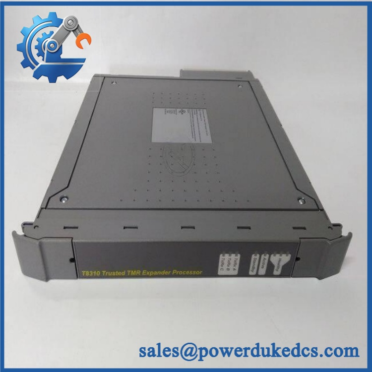
ICS Triplex T8310
Module 4: Compatibility & Replacement Matrix (Crucial for Buyers)
| Purchase / Migration Case | Compatibility Assessment | Typical Switch Effort |
|---|---|---|
| Replace T8310 with the same T8310 revision in an existing Trusted Expander Chassis | Drop-in Replacement | 30–90 minutes, subject to approved hot-swap procedure |
| Replace with another approved revision | Software Compatible — Engineering Verification Required | 1–3 hours |
| Replace one in an active/standby arrangement | Drop-in Replacement, provided the standby architecture and revision are compatible | 30–90 minutes |
| Substitute another Trusted processor family | Hardware Modification | 4–16+ hours |
| Migrate the Trusted Expander architecture to another safety platform | Hardware Modification + Software Conversion | Several days to weeks |
The uses TMR/HIFT fault tolerance, and its application depends on the Trusted Expander Chassis, the Expander Interface Module, and the associated communications link. The documented architecture also supports hot replacement and standby configurations.
Field Traps — Watch Out
Chassis Position: The is intended for the processor positions of the Trusted Expander Chassis. Do not treat it as a generic plug-in module for every Trusted chassis location. The module and associated connector/cable assemblies are mechanically keyed to prevent incorrect insertion.
Expander Interface Compatibility: Verify the installed T8312 Expander Interface Adapter and TC-301 hot-link cable arrangement. These components form part of the communications path to the controller assembly.
Module 5: Quality Assurance & Testing SOP
1. Part Identity Verification
Record the exact part number, serial number, hardware revision, manufacturer markings, and available date/lot information. Photograph the identification label before testing.
2. OEM Anti-Counterfeit Visual Inspection
Inspect the front panel, LEDs, card-edge connector, PCB markings, labeling, connector geometry, fasteners, and module construction. Compare the hardware against known Trusted characteristics.
3. Mechanical Inspection
Check the PCB, card guides, connector contacts, mounting structure, keying arrangement, and module housing. Reject units with corrosion, contamination, cracked PCB material, bent contacts, or evidence of unauthorized modification.
4. Electrical Pre-Test
Verify ground continuity and inspect the DC input path. Check for unintended shorts before inserting the processor into a powered test chassis.
5. Power-On Self-Test (POST)
Install the in a compatible Trusted Expander Chassis and apply controlled DC power. Verify the three Healthy indicators, Active/Standby indication, and the three communications TxRx indicators. The documented LED scheme uses three health indicators for the TMR slices and three communication indicators for the processor channels.
6. TMR Slice Diagnostic Test
Verify that all three processor slices initialize correctly and report healthy status. Confirm that no individual slice remains in a fault state after startup or controlled reset.
7. Expander Bus Communication Test
Connect the through the appropriate Trusted Expander Interface arrangement. Verify communications across the triplicated Expander Bus and confirm expected Tx/Rx activity.
8. Active/Standby Test
Where the test platform permits, verify active and standby state reporting. Confirm that the standby configuration behaves correctly without generating spurious system faults.
9. 24 VDC Supply Monitoring
Verify operation across the applicable DC supply range and confirm that the module reports supply status correctly. The published specification gives a 20–32 VDC operating range.
10. Extended Burn-In
Operate the module under representative communication load while monitoring all three health channels, Active/Standby status, communication activity, supply stability, and intermittent diagnostic events.
11. Final QC Record
Document hardware revision, serial number, POST results, TMR-slice status, communication test results, supply measurements, burn-in outcome, and final QC disposition. Package using ESD-safe protection.
Module 6: Procurement & Lifecycle FAQ
Q1. Is the ICS Triplex genuinely in stock, and what is the cutoff for emergency shipping?
The is legacy Trusted hardware, so actual physical inventory should be confirmed before an emergency PO. Current technical and supplier references continue to identify the as the Trusted TMR Expander Processor, but published technical documentation does not establish live stock availability.
Q2. How do you guarantee the condition and authenticity of an obsolete or surplus ?
Require complete part-number and revision inspection, OEM-style visual verification, connector and PCB inspection, controlled power-up, three-channel TMR health verification, Expander Bus communication testing, Active/Standby verification, and a documented burn-in report.
Q3. Are there firmware compatibility issues I should warn my engineers about before issuing the PO?
Yes. The exact hardware revision and installed Trusted system configuration should be verified before substitution. Engineers should check the TMR processor arrangement, Trusted Expander Chassis, T8312 interface adapter, TC-301 communications connection, and the applicable system software/revision. The is not an isolated generic communications module.
Q4. Can I replace with another Trusted processor module?
No automatic substitution should be assumed. is specifically the Trusted TMR Expander Processor, designed for the Expander Chassis and its associated triplicated communications architecture. A different Trusted processor requires an engineering compatibility assessment.
Q5. What warranty and return terms should procurement require?
Specify a written functional warranty and RMA process covering TMR-slice startup, Healthy indication, Expander Bus communication, Active/Standby operation, and stable operation under the stated test conditions. The PO should also define exclusions for incorrect chassis installation, damaged keyed connectors, improper power, and customer-side wiring or communications faults.











 Start Chat


