

Description
- Model & Brand: CMA-RM1 / Metso-Dametric RMS
- SKC Number: 9315772
- Product Type: CMD motor-driver adapter module
- System Family: Dametric RMS / Series 23
- Physical Dimensions: Exact OEM dimensions not published in the available installation document; verify cabinet drawing before freight booking
- Estimated Shipping Weight: Approx. 0.3–0.7 kg packed; confirm actual packed weight before commercial quotation
- Mechanical Construction: PCB-based adapter with a dedicated card-guide/front-panel arrangement
- What’s in the Box: CMA-RM1 adapter assembly; mounting hardware/guide components only when included with the supplied configuration; documentation only when specifically stated
- Installation Hardware: Extra card guide rail, 3 × 5 mm mounting screw, plate, and cable-retention straps are referenced in the OEM assembly procedure
- Related Hardware: CMD-RM1 control motor driver and CMI-RM1 interface card
- Handling: ESD-protected packaging recommended for storage and transport
Dametric’s installation document identifies CMA-RM1 as a “CMD ADAPTOR” and instructs the technician to install an additional card-guide rail, secure the new assembly with a 3 × 5 mm screw and plate, and use two plastic straps to retain nearby cabling.
Product Introduction
The CMA-RM1 is physical interface hardware inside the RMS cabinet, not a standalone process controller. Its documented purpose is to adapt the CMD-RM1 installation within the relevant Dametric RMS assembly. The OEM procedure requires the technician to remove the CMD-RM1, CMI-RM1, and nearby cards to create installation space, then fit the additional guide rail before installing the adapter assembly.
For maintenance planning, that distinction is important. The CMA-RM1 should be sourced as an exact mechanical/electrical adapter, not selected merely because another RMS card carries an “RM1” designation. The available OEM document also shows that cable routing is part of the installation procedure, with two plastic straps used to prevent cables from catching on adjacent cards (a small detail that can become a recurring cabinet-maintenance problem).
Core Technical Specifications
| Parameter | Value |
|---|---|
| Model | CMA-RM1 |
| Manufacturer | Dametric / Metso RMS ecosystem |
| SKC Number | 9315772 |
| Product Type | CMD Adapter Module |
| Primary Associated Module | CMD-RM1 |
| Related Interface | CMI-RM1 |
| System | RMS / Series 23 |
| Function | Mechanical/electrical adaptation of CMD-RM1 within the RMS card assembly |
| Installation | Internal RMS cabinet/card-guide assembly |
| Mounting Hardware | 3 × 5 mm screw and plate referenced by OEM procedure |
| Cable Retention | Two plastic straps specified in installation procedure |
| Firmware | None identified for the adapter itself |
| Processor | None identified |
| Physical Dimensions | OEM dimensions not established from the available documentation |
| Net Weight | OEM value not established |
| Shipping Weight | Supplier packaging dependent |
| Storage Classification | Electronic PCB assembly; ESD-controlled handling recommended |
The OEM installation instruction provides the clearest verified information about this component: it is a CMD adapter, is installed alongside the CMD-RM1/CMI-RM1 hardware, and requires a dedicated guide-rail modification.
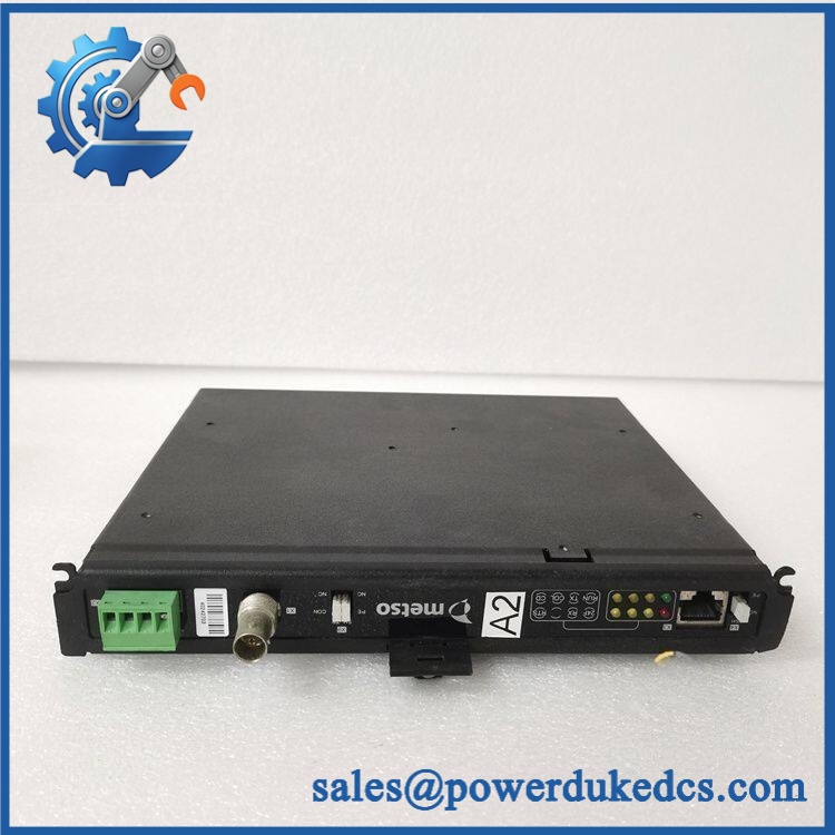
Metso CMA-RM1 SKC9315772
🚨 Global Compliance & Industry Certifications
For the , certification claims should be handled conservatively because the available OEM material identifies the part primarily as an internal RMS adapter assembly rather than as an independently certified field instrument.
- CE Mark: May be applicable at the complete RMS equipment/system level. Do not claim independent CE marking for the without manufacturer documentation.
- UL/cUL: No reliable independent UL/cUL listing was established for .
- ATEX / IECEx: No evidence was established that itself carries ATEX or IECEx certification.
- Marine Approvals: No DNV, ABS, or Lloyd’s Register approval was established for the individual adapter.
- EMC: EMC compliance should be evaluated against the complete RMS assembly and cabinet installation rather than inferred from the adapter board alone.
Why this matters: An adapter board may sit inside a larger CE-compliant control system, but that does not automatically make the individual board a separately certified hazardous-area component.
Verify specific lot certifications with OEM.
🚨 Long-Term Storage & Asset Preservation Guide
Keep the sealed in ESD shielding material. This is an internal electronic assembly, and repeated exposure to handling, dust, and humidity can attack connector surfaces and solder joints over long storage periods. Do not store the board loose on a metal shelf.
Control warehouse humidity. A practical preservation target is below 60% RH, without condensation. For older RMS inventory, stable temperature is preferable to repeated hot/cold cycling because condensation can form on connector contacts even when the average warehouse humidity appears acceptable.
Inspect the mechanical hardware separately. The OEM installation procedure relies on the guide rail, mounting screw/plate, and cable-retention straps. Store those pieces with the adapter rather than treating them as disposable installation accessories. A missing mounting component can turn an otherwise usable spare into a cabinet-work delay.
Before energization after multi-year storage, inspect PCB solder joints, connector contacts, mounting points, and any exposed hardware for oxidation or contamination. Allow cold-shipped material to reach room temperature before opening the ESD package.
Physical Installation Prerequisites
- Cabinet Location: Install within the designated Dametric RMS card assembly; this is not a free-standing DIN-rail module.
- Guide Rail: The OEM procedure specifically calls for an additional card-guide rail at the specified assembly position.
- Mounting Hardware: Use the specified 3 × 5 mm screw and plate where applicable.
- Adjacent Card Clearance: Remove the , CMI-RM1, and nearby card during installation to obtain working clearance, then reinstall them after the adapter is secured.
- Cable Routing: Keep cables clear of adjacent card edges and secure them with the two specified plastic straps.
- Grounding: Follow the grounding arrangement of the host RMS cabinet; do not create an independent grounding scheme without reference to the cabinet drawing.
- Cooling: No separate airflow specification was established. Preserve the host rack’s designed ventilation path and avoid tightly packing cables around the PCB.
- ESD: Use a grounded wrist strap and an ESD-safe work surface during installation and removal.
- Final Mechanical Check: Confirm the adapter is fully seated and firmly retained before reinstalling surrounding cards.
The available Dametric procedure explicitly warns that the system must be powered off before assembly work begins.
Buyer’s FAQ
Q1. What HS tariff code should we use for SKC9315772?
Do not assign a final HS code solely from the model number. Because is an electronic adapter assembly rather than a complete control cabinet, classification may depend on whether customs treats it as a part of control equipment or as an electronic circuit assembly. A broker should validate the code using the commercial description, technical function, and destination-country tariff schedule.
Q2. What should be shown on the Country of Origin documentation?
Use the actual manufacturing origin supported by supplier or manufacturer records. Sweden-origin shipment, warehouse location, and Country of Origin are not interchangeable concepts. Retain the invoice, packing list, COO statement/certificate when applicable, part-number photographs, and serial or lot traceability for the audit file.
Q3. Is safe to hot-swap?
No live replacement should be assumed. The OEM installation procedure explicitly begins with turning system power off, followed by removal of , CMI-RM1, and nearby cards before installing the adapter. Follow the documented maintenance procedure rather than treating the card as a hot-pluggable module.
Q4. Does contain the latest firmware? What warranty should apply?
No adapter-specific firmware package is identified in the available OEM installation material; this component is documented as a CMD adapter assembly rather than a programmable controller. For surplus stock, the warranty should cover physical integrity, correct part identity, mechanical fit, and functional operation within the intended RMS installation. Request serial/lot photographs and pre-shipment inspection evidence before release.











 Start Chat


