

Description
- Model: CMI-RM1
- Brand: Metso / Dametric RMS
- Metso VAL Number: VAL0122828
- SKC Number: SKC9068191
- System: RMS / RMS-EX1 Refiner Monitor System
- Part Type: Control Motor Interface module
- Primary Function: Converts PLC control commands into clock and direction signals for the CMD-RM1/CMD-RM2 stepping-motor driver.
- Physical Dimensions: The reviewed CMI-RM1 documentation does not provide a reliable dimensional drawing for this specific card; do not substitute dimensions from another RMS module.
- Estimated Shipping Weight: Not reliably published; confirm actual packed weight from the warehouse packout before freight quoting.
- What’s in the Box: CMI-RM1 module; ESD shielding protection; protective carton; manuals, mating connectors, and cables only when specifically stated in the purchase order.
- Associated Driver: CMD-RM1 or CMD-RM2
- Rack Interface: Internal RMS rack PCB connectors; external PLC signals are brought into the RMS system through the rack’s terminal architecture.
Product Introduction
The CMI-RM1 sits between the plant PLC and the refiner’s motor-positioning hardware. Within the RMS-EX1 architecture, the Control Motor Interface receives commands from the PLC and converts them into the clock and direction signals required by the CMD-RM1/CMD-RM2 stepping-motor driver. The driver then supplies current to the two-phase electric stepping motor controlling the refiner rotor position. The CMI-RM1 is therefore an interface/controller card, not the motor-current amplifier itself.
The documented identification is CMI-RM1 / Metso VAL0122828 / SKC9068191. Its specified input power is +24 VDC ±10%, maximum 0.14 A, with isolated internal +12 VDC and -12 VDC supplies. The RMS documentation also records software-dependent support for both CMD-RM1 and CMD-RM2; the later controller combination requires the applicable RMS software version.This distinction matters during legacy maintenance because replacing the CMI card will not correct a failed CMD power stage or a mechanically jammed stepping motor (the fault may sit downstream).
Core Technical Specifications
| Parameter | Value |
|---|---|
| Manufacturer | Metso / Dametric |
| Model | |
| Metso VAL No. | VAL0122828 |
| SKC No. | SKC9068191 |
| System | RMS / RMS-EX1 |
| Part Type | Control Motor Interface |
| Core Function | Converts PLC control signals to clock and direction signals |
| Compatible Driver | CMD-RM1 / CMD-RM2 |
| Supply Voltage | +24 VDC ±10% |
| Maximum Current Consumption | 0.14 A |
| Internal Supply Rails | +12 VDC and -12 VDC |
| Internal Supply Isolation | Isolated from input supply |
| PLC Interface | Digital control signals |
| Motor Interface | Clock/direction control to CMD-RM1/CMD-RM2 |
| Motor Type Controlled | Two-phase electric stepping motor, through CMD driver |
| Typical RMS Application | Refiner rotor-position control |
| Configuration Functions | Refiner type / pitch selection; controller selection |
| Rack Architecture | RMS internal card |
| Environmental Protection | Installed within protected RMS cabinet |
| Firmware Status | Software-dependent system compatibility; card-specific firmware version not established in reviewed documentation |
The original manual identifies the exact VAL0122828 / SKC9068191 part number and specifies the electrical supply and isolated internal rails.The RMS-EX1 manual places directly between the PLC control interface and CMD stepping-motor driver
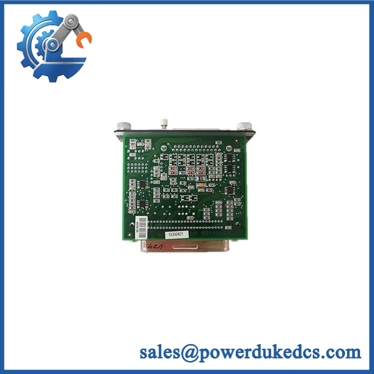
Metso CMI-RM1 VAL0122828 SKC9068191
🚨 Global Compliance & Industry Certifications
The available documentation provides system-level CE information for the RMS-EX1, rather than a separate certification claim specifically for the circuit board. The RMS-EX1 documentation references EN 50081-2:1993, EN 50082-2:1995, and 89/336/EEC, with test report Enator TR976011.
For an audit file:
- CE Mark: Applicable certification evidence is documented at the system level. The standalone card should not be represented as independently CE-certified without supporting documentation.
- UL/cUL: No -specific UL/cUL listing was established from the reviewed records.
- ATEX/IECEx: No standalone ATEX or IECEx certification was established. The card is documented as an internal RMS control module.
- Marine Approval: No -specific DNV, ABS, or Lloyd’s Register approval was established.
- EMC: documentation references EN 50081-2 and EN 50082-2.
- Hazardous-Area Use: Do not infer hazardous-area suitability from the RMS product name. Verify the complete cabinet and installation certification.
Verify specific lot certifications with OEM.
🚨 Long-Term Storage & Asset Preservation Guide
Keep the sealed in an ESD shielding bag. This is a mixed analog/digital interface card with board-level power conversion and signal-conditioning circuitry; edge contacts and exposed PCB surfaces should remain protected until installation.
Control moisture aggressively. The system is specified for 15–95% relative humidity, non-condensing, with a storage range of -40 to +70 °C. For long-term spare storage, maintaining the warehouse near or below 60% RH provides additional margin against condensation and contact oxidation. Avoid repeated cold-to-warm transfers without allowing the sealed package to reach ambient temperature.
Record switch and configuration settings before shelving. The documentation includes configuration settings associated with refiner type and controller selection.Photograph DIP-switch positions and any visible board revision before packing the card away. That record can save commissioning time years later.
Do not invent a capacitor-reforming schedule. No two-year reforming procedure for is established in the reviewed manufacturer documentation. Controlled bench testing before deployment is the more defensible preservation practice.
Physical Installation Prerequisites
The is an internal RMS rack module, not a standalone DIN-rail device. The rack uses internal PCB connectors for its installed modules, with separate terminal blocks for external signals.
Before installation:
- Confirm the host system is an installation.
- Verify the card location against the approved rack configuration.
- Inspect the internal PCB connector for oxidation, bent contacts, debris, or mechanical damage.
- Confirm the RMS system supply is 24 VDC ±10%.
- Check that the CMI interface is being used with the correct or driver.
- Verify the installed PLC command wiring before inserting the replacement card.
- Preserve the existing configuration-switch settings.
- Ensure the rack is mounted inside its protective cabinet. The documentation specifies vertical mounting on a mounting plate using four M6 screws for the system cabinet.
- Follow the cabinet’s established grounding arrangement; RMS documentation states that cable shields connect directly to the ground bar and the rack is grounded through its ground cable.Do not impose a generic 50 mm clearance requirement on the card itself. Cooling and spacing must follow the RMS cabinet arrangement because the is part of a rack assembly rather than a free-standing enclosure.
Buyer’s FAQ
Q1. What HS tariff code should be used for ?
A: Avoid assigning a final tariff number from the description alone. is an electronic control-interface card for an industrial refiner-monitoring system, so the classification can depend on the importing country’s tariff schedule and the declared function. HS heading 8537 or 9031 may be considered depending on the customs interpretation, but the final classification should be confirmed by the importer or customs broker before shipment.
Q2. Does the Country of Origin depend on whether the part is stored in a Metso facility?
A: No. Country of Origin concerns where the physical component was manufactured or acquired according to applicable origin rules, not the country from which the spare is dispatched. For an audit-ready file, retain the actual unit identification, supplier origin declaration, commercial invoice, and Certificate of Origin where required.
Q3. How should I pack a for international freight?
A: Use an ESD shielding bag, connector protection, rigid internal cushioning, and a carton that prevents the PCB from shifting during transit. The itself operates inside a protected cabinet, so the spare should receive equivalent protection during logistics handling. Because the specific shipping weight is not reliably published, use the actual packed weight and dimensions for freight booking rather than a catalog estimate.
Q4. Does come with the latest firmware pre-loaded?
A: Do not assume that a stored spare contains a current software revision. The available documentation describes the module’s signal-conversion function and configuration settings, while system compatibility depends partly on the RMS software generation and whether or is being used.Record the existing system revision before commissioning a replacement.
Q5. Is interchangeable with ?
A: No. They perform different functions. converts PLC commands into clock/direction signals; is the current driver that supplies the two-phase stepping-motor drive current. (manualzz.com) Replacing one with the other would be a hardware-level error, not a normal spare-card substitution.











 Start Chat


