

Description
- Model & Brand: Metso MPM-RM2 / VAL0122979 / SKC9374469
- Product Type: Motor Power Monitor for the RMS refiner monitoring system
- PCB Dimensions: Approx. 220 × 100 × 30 mm (L × W × T)
- Rack Format: Approximately 6 TE module width
- Estimated Shipping Weight: Approx. 0.5–0.8 kg packed, depending on ESD protection and export cushioning
- Electrical Supply: +24 VDC ±10%
- Typical Supply Current: 0.18 A maximum
- What’s in the Box: MPM-RM2 board; protective ESD packaging; identification materials; manual only when specifically included with the offered unit
- Field Interface: 4–20 mA input, isolated 4–20 mA analog output, three digital limit outputs
- Related RMS Equipment: LDU-RM1, DCU-RM1/2, PLC interface
- Storage Note: Confirm actual board revision and component condition before long-term stocking
The technical manual identifies MPM-RM2, Metso part VAL0122979, and SKC 9374469 as the motor power monitor for the RMS system. It specifies a 220 × 100 × 30 mm board and 24 VDC ±10% supply with maximum current of 0.18 A.
Product Introduction
Refiner motor loading can change before the mechanical problem becomes obvious at the machine. The Metso MPM-RM2 continuously monitors the main refiner motor power from the high-voltage motor switchgear current signal and generates scaled process information for the RMS system. Its functions include zero/span adjustment, an isolated 4–20 mA analog output, a 1–5 V display output, and three adjustable limit circuits.
Physically, this is a compact control board intended for installation inside the RMS cabinet rather than as a standalone industrial enclosure. The board uses a 24 VDC isolated DC/DC supply to generate internal +12 V and -12 V rails, while the limit outputs use optically isolated P-channel transistor stages. (The hardware dates from a much earlier RMS generation, so preservation of configuration records is important when replacing field stock.)
Core Technical Specifications
| Parameter | Value |
|---|---|
| Model | MPM-RM2 |
| Metso Part Number | VAL0122979 |
| SKC Number | 9374469 |
| Function | Motor Power Monitor |
| System | RMS Refiner Monitoring System |
| Supply | +24 VDC ±10% |
| Maximum Supply Current | 0.18 A |
| Internal Supply | Isolated +12 VDC / -12 VDC |
| Board Length | 220 mm |
| Board Width | 100 mm |
| Board Thickness | 30 mm |
| Rack Width | 6 TE |
| Input Signal | 4–20 mA |
| Low-Current Trip | 3.0 mA |
| Input Impedance | 100 Ω |
| Analog Output | Galvanically isolated 4–20 mA |
| Analog Output Accuracy | ±0.5% |
| Analog Output Load | 0–800 Ω |
| Analog Output Isolation | Up to 500 V |
| Display Output | 1–5 V |
| Digital Outputs | 3 isolated limit outputs |
| Digital Output Current | Maximum 0.1 A |
| Limit 1 / 2 | 0–100% signal span |
| Limit 3 | 0–100% of motor rated power |
| Limit 3 Time Setting | 0–10.0 s |
| Limit 3 Pulse Duration | ≥5 s |
| Limit Hysteresis | 2% on rising activation |
| RMS Interface | Yes |
The published manual specifies the 4–20 mA input, 3.0 mA low-current threshold, 100 Ω input impedance, isolated 4–20 mA output, 0–800 Ω output load, three digital limit outputs, and the stated board dimensions.
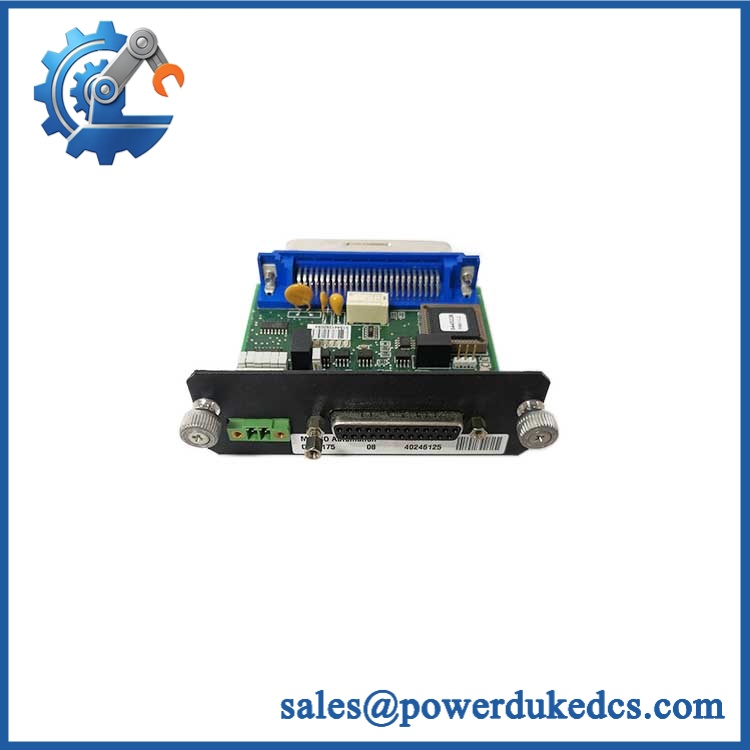
Metso MPM-RM2 VAL0122979 SKC9374469
🚨 Global Compliance & Industry Certifications
For this type of installed RMS monitoring board, the compliance file should be tied to the complete Metso/Dametric RMS installation, not inferred solely from the MPM-RM2 circuit board.
- CE Mark: The related RMS-SD1 system documentation identifies CE compliance against EN 50081-2, EN 50082-2, and 89/336/EEC for the RMS equipment family. The exact board should not be represented as independently CE-marked without supporting documentation.
- UL/cUL: No reliable evidence was found establishing independent UL/cUL listing for the board.
- ATEX / IECEx: No evidence was found establishing an ATEX or IECEx approval for the itself. Do not use the board as hazardous-area equipment without a documented system-level assessment.
- Marine Approvals: No DNV, ABS, or LR approval was established for this board from the available technical records.
- Industrial EMC: The RMS documentation includes CE-related EMC requirements at the system level.
Why this matters: EMC compliance is not cosmetic. A poorly controlled analog measurement circuit can introduce false motor-power readings, unwanted limit activation, or unstable PLC indications.
Verify specific lot certifications with OEM.
🚨 Long-Term Storage & Asset Preservation Guide
Keep the in sealed ESD shielding material. This is an exposed PCB rather than a fully enclosed industrial instrument. Protect the gold-plated or tin-plated connector surfaces from fingerprints, sulfur contamination, and humidity; do not stack heavy hardware directly on the board.
Control warehouse humidity. A practical target is below 60% RH, with no condensation. The published RMS system documentation permits a broad non-condensing humidity range, but long-term spare preservation should use a more conservative environment, particularly for older boards with decades-old solder joints and electrolytic capacitors.
Inspect aged components before energization. Look closely at electrolytic capacitors, relays or semiconductor output stages, trim potentiometers P1/P2, terminal connections, and PCB solder joints. Do not immediately connect a decades-old board to a production RMS rack after cold storage; allow it to reach room temperature inside its sealed package first.
The manual specifically identifies P1 ZERO and P2 SPAN as factory-adjustment potentiometers and warns that these settings normally should not require field adjustment after delivery.
Physical Installation Prerequisites
- Mounting: Install the in the designated RMS rack or approved mounting assembly; the board is approximately 220 × 100 × 30 mm and occupies roughly 6 TE.
- Clearance: Preserve sufficient space around the board for connector access and cabinet airflow. Do not press adjacent wiring bundles against the PCB.
- Power: Provide 24 VDC ±10% through the approved RMS supply arrangement. Maximum specified board current is 0.18 A.
- Grounding: Follow the RMS rack grounding arrangement. The related RMS documentation states that cable shields connect directly to the ground bar and the rack is grounded through its ground cable.
- Signal Wiring: Keep the 4–20 mA motor-current-derived signal wiring separated from noisy switching conductors.
- PLC Outputs: Verify the three limit outputs against the approved PLC termination drawing before energization.
- Adjustment Access: P1 and P2 are accessible from the top of the board; these controls should remain sealed or documented after calibration where the site procedure requires configuration control.
- Thermal Environment: Keep the cabinet within the applicable RMS environmental specification and prevent localized heating from adjacent power equipment.
Buyer’s FAQ
Q1. What HS tariff code should be used for international shipment of VAL0122979?
A final HS classification should be confirmed by the customs broker from the actual commercial description and function. Historical trade records have classified a VAL0122979 circuit/control board under heading 8537 in some shipments, while other electronic-board classifications can fall under different headings depending on construction and declared function. Do not copy an old tariff line without reviewing the current destination-country tariff schedule.
Q2. How should Country of Origin be documented?
Record the actual manufacturing origin shown on the supplier’s supporting documentation and, where available, the OEM-origin statement. Shipping location is not the same as COO. For audit retention, keep the invoice, packing list, COO documentation, serial/part-number photographs, and any manufacturer traceability documents together.
Q3. Is shipping insurance worth adding for a 320 g class circuit board?
Yes when the replacement value and outage consequence are significant. The is physically small, but the operational cost of losing a refiner motor-power monitoring channel can greatly exceed the freight value. Use ESD shielding plus rigid cushioning, and insure the shipment for the documented commercial replacement value.
Q4. Does the include the latest firmware pre-loaded?
There is no modern firmware image that should be assumed for this board. The 1997 manual describes analog circuitry, potentiometer calibration, discrete limit logic, and an isolated DC/DC supply rather than a firmware-managed controller. For a replacement, configuration and calibration records matter more than a firmware version.











 Start Chat


