

Description
- Model: TVD-RM3
- Brand: Metso
- Metso VAL Number: VAL0123117
- SKC Number: SKC9251496
- System: RMS-EX / RMS-EX1 Refiner Monitoring System
- Part Type: Touchpoint vibration detector / monitor module
- Physical Dimensions: Approx. 220 × 100 × 30 mm (L × W × T); 6 HE rack-card format. ([turn175390search0])
- Estimated Net Weight: Approximately 0.3–0.5 kg, depending on the installed front hardware and connector arrangement
- Estimated Shipping Weight: Approximately 0.7–1.0 kg with ESD protection and carton
- What’s in the Box: TVD-RM3 monitor module; ESD protection; standard packing; manuals or mating cables only when explicitly included in the purchase order
- Associated Cable: K-TVDS25, Metso VAL0122971, SKC9305689. ([turn175390search1])
- Supported Transducers: TVD-T2, TVD-T2S, and TVD-T3 configurations are documented for the RMS-EX system. ([turn175390search1])
Product Introduction
The physical rack architecture matters here. TVD-RM3 is an internal card in the RMS-EX1 refiner monitoring rack, alongside the VIM-RM1 vibration monitor, MPM-RM1 motor power monitor, POM-RM1 position monitor, and other dedicated monitoring cards. The documented assembly size is 220 mm long, 100 mm wide, and 30 mm thick, with a 6 HE card format. ([turn175390search0]) In the system parts list, Metso VAL0123117 and SKC9251496 identify the same TVD-RM3 touchpoint vibration detector. ([turn175390search1])
The module excites and measures a piezoelectric accelerometer associated with the refiner touchpoint. Documented compatible transducers include TVD-T2, TVD-T2S, and TVD-T3, while the associated cable is K-TVDS25. The electronics operate from +24 VDC ±10%, with maximum current consumption of approximately 0.19 A, and generate isolated internal ±12 V rails. ([turn175390search0]) For legacy RMS-EX installations, that exact card-and-transducer combination is important (especially when spare inventory has been sitting for years).
Core Technical Specifications
| Parameter | Value |
|---|---|
| Manufacturer | Metso |
| Product | TVD-RM3 |
| Metso VAL No. | VAL0123117 |
| SKC No. | SKC9251496 |
| System | RMS-EX / RMS-EX1 |
| Function | Touchpoint vibration monitor/detector |
| Supply Voltage | +24 VDC ±10% |
| Maximum Current | 0.19 A |
| Internal Supply | ±12 VDC, isolated from input supply |
| PCB / Module Dimensions | 220 × 100 × 30 mm |
| Rack Format | 6 HE |
| Sensor Type | Low-impedance piezoelectric accelerometer |
| Compatible Transducers | TVD-T1/T2 family, including TVD-T2S and TVD-T3 |
| Sensor Excitation | 10 mA constant current, approximately 20 VDC |
| Sensor Input Impedance | 50 kΩ |
| Short-Circuit Trip Resistance | 315 Ω |
| Open-Circuit Trip Resistance | 2.95 kΩ |
| AC Signal Gain | 0.1–20, internally adjustable |
| Low-Pass Filter | Active, 12 dB/octave |
| Filter Bandwidth | Approximately 300 Hz to 10–40 kHz, DIP-selectable |
| Gain Adjustment | Front-panel potentiometer |
| Limit Outputs | Limit 1 and Limit 2 |
| Limit Indication | Green LEDs |
| High-Gain Indication | Yellow LED |
| Signal Display | 10-segment LED bar |
| Analog Output | 4–20 mA DC |
| Audio Output | AC signal to headset |
| System Interface | Internal RMS-EX rack connectors |
| Associated Cable | K-TVDS25 |
| Typical Storage Context | RMS-EX1 protected cabinet |
| Documentation Date | March 1, 2003 manual; later RMS-EX1 documentation continues to identify the same part numbers |
The 2003 TVD-RM3 manual gives the module electrical and mechanical characteristics, while the later RMS-EX1 manual confirms the VAL0123117 / SKC9251496 cross-reference and associated sensor/cable hardware. ([turn175390search0] [turn175390search1])
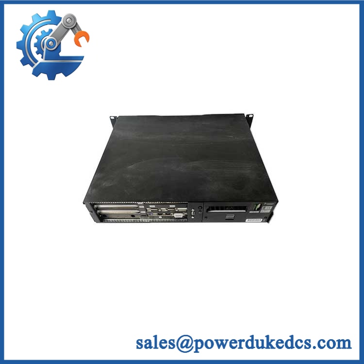
Metso TVD-RM3 VAL0123117 SKC9251496
🚨 Global Compliance & Industry Certifications
The available system documentation identifies CE approval for the installation, citing EN 50081-2:1993, EN 50082-2:1995, and 89/336/EEC, with a referenced test report. The same documentation identifies the system as a protected cabinet assembly rather than assigning a separate hazardous-area certification to every plug-in card. ([turn175390search2])
For compliance records:
- CE Mark: The system documentation provides CE-related EMC information. This supports an audit trail for the system, but it should not be interpreted automatically as a standalone CE declaration for every spare.
- UL/cUL: No reliable -specific UL/cUL listing was established from the documentation reviewed.
- ATEX/IECEx: The reviewed records do not establish a standalone ATEX or IECEx certificate for .
- Marine approvals: No -specific DNV, ABS, or LR approval was established from the available records.
- EMC: The system documentation references EN 50081-2 / EN 50082-2 requirements. ([turn175390search2])
A system-level CE declaration can matter during an audit because replacing a field-installed safety or monitoring component with an unverified substitute may invalidate the documented hardware configuration. Verify specific lot certifications with OEM.
🚨 Long-Term Storage & Asset Preservation Guide
Keep the card inside an ESD shielding bag during storage. contains analog amplification, sensor-excitation circuitry, adjustable gain components, DIP switches, and connectors; repeated unpacking and handling can contaminate contacts or expose the circuitry to electrostatic discharge.
Control humidity and condensation. The system documentation specifies non-condensing environmental conditions, with an overall system storage range of approximately -40 to +70 °C and humidity specified as 15–95% non-condensing. ([turn175390search1] [turn175390search2]) For warehouse preservation, keeping relative humidity below roughly 60% RH is a prudent internal target, particularly where the card may later be moved into a warmer plant environment.
Record the configuration before shelf storage. Photograph the DIP-switch positions, front-panel potentiometer settings, labels, and board revision. uses switch-selectable sensor/filter configuration and adjustable gain, so losing the original setup can create commissioning work even when the hardware itself tests correctly. ([turn175390search0])
Do not assume a capacitor-reforming schedule. The available documentation does not prescribe a two-year capacitor-reforming procedure. A dormant module should instead receive controlled bench testing before being released to a critical application.
Physical Installation Prerequisites
is not a DIN-rail power module. It is an internal card designed for the , using the rack’s PCB connectors and protected-cabinet arrangement. The associated system uses dedicated internal connectors for the monitoring cards. ([turn175390search1])
Before installation:
- Confirm the receiving rack is the correct architecture.
- Verify the card position against the approved rack layout.
- Check the mating internal connector for oxidation, contamination, bent contacts, or mechanical damage.
- Confirm the system provides +24 VDC ±10% and sufficient current capacity.
- Verify the installed transducer is one of the documented TVD-compatible types.
- Confirm the K-TVDS25 cable and connector arrangement where applicable. ([turn175390search1])
- Preserve the original DIP-switch settings and front-panel gain configuration.
- The rack itself should remain inside the intended protected cabinet; the documentation specifies cabinet mounting and system grounding provisions. ([turn175390search2])
- Use the rack’s mechanical guides and retaining hardware; do not force the 30 mm card into a connector.
- Allow sufficient cabinet airflow for the complete assembly. The documentation does not provide a universal 50 mm top-and-bottom clearance rule, so use the cabinet manufacturer’s specified ventilation arrangement rather than inventing a generic clearance value.
- Connect cable shields according to the grounding scheme; the system documentation states that cable shields are connected directly to the ground bar. ([turn175390search2])
Buyer’s FAQ
Q1. What HS tariff code should be used for during international shipment?
A: Avoid assigning a final HS code from the product name alone. is an electronic vibration-monitoring card used within an industrial process-monitoring system, so the appropriate classification depends on the importing country’s tariff schedule and the exact commercial description. HS heading 9031 may be a candidate for instruments used to measure or check physical variables, but the final classification should be confirmed by the importer or customs broker.
Q2. Does the Country of Origin need to match the Metso warehouse location?
A: No. COO refers to the manufacturing origin of the actual item, not where the spare happens to be stored. For an audit-ready shipment, record the physical product’s origin from the nameplate, traceability record, or supplier declaration, then keep the same origin information on the commercial invoice and Certificate of Origin when required.
Q3. How should a 220 × 100 × 30 mm be packed for international freight?
A: Use an ESD shielding bag, protect the connector edge and front-panel components, immobilize the card inside a rigid inner pack, and use shock-resistant external packaging. Do not allow the module to move freely inside the carton. For high-value shutdown spares, shipping insurance should cover the declared replacement value and the carrier’s applicable damage/loss conditions.
Q4. Does include the latest firmware pre-loaded?
A: No conventional firmware-loading assumption should be made for this legacy analog monitoring card. The available documentation describes analog signal processing, DIP-switch configuration, potentiometer gain adjustment, LED indication, and discrete/analog outputs, rather than a field-loaded firmware platform. ([turn175390search0]) Before installation, compare the physical board revision and recorded DIP/gain settings with the existing RMS-EX configuration.
Q5. Is VAL0123117 the same item as SKC9251496?
A: Yes. The system parts list explicitly cross-references → Metso VAL0123117 → SKC9251496. ([turn175390search1]) For procurement and customs records, retain both identifies because they provide useful cross-reference evidence for warehouse and audit reconciliation.











 Start Chat


