

Description
- Brand: ALSTOM
- Full Model Number: POS1846 / TRVC062333000 / CP00000310
- System/Series Family: ALSTOM railway control electronics
- Core Function: Processor and control interface board for a legacy ALSTOM railway electronic control assembly
- Top 3 Hardcore Specs: POS1846 board designation; TRVC062333000 assembly identifier; CP00000310 configuration code
- Board Type: Control / processor electronics assembly
- Hardware Identifier: TRVC062333000
- Configuration Identifier: CP00000310
- Installation: Rack or chassis-mounted electronic assembly
- Communication: System-dependent internal control and backplane interfaces
- Stock Status: New Surplus or Fully Tested Refurbished; exact hardware revision to be confirmed
Module 3: Technical Product Introduction
A railway control cabinet can remain mechanically intact while a single controller board becomes the reason an entire subsystem is unavailable. The ALSTOM POS1846, identified by TRVC062333000 and CP00000310, is a revision-controlled electronic control assembly associated with ALSTOM railway equipment. The three identifiers should be kept together because they define more than a generic POS1846 family reference. For replacement work, the board’s physical configuration, installed firmware, connector arrangement, and host equipment are more important than the short model designation alone.
Technical data for this exact combination are limited in publicly indexed sources. I could not independently verify processor type, memory capacity, supply voltage, power consumption, operating-temperature range, communication protocol, or connector pinout to a manufacturer-level standard. Those figures should therefore not be filled in from unrelated ALSTOM boards. In legacy railway equipment, a superficially similar control board can use different firmware, address coding, backplane assignments, or safety-related configuration — even when the PCB dimensions are identical.
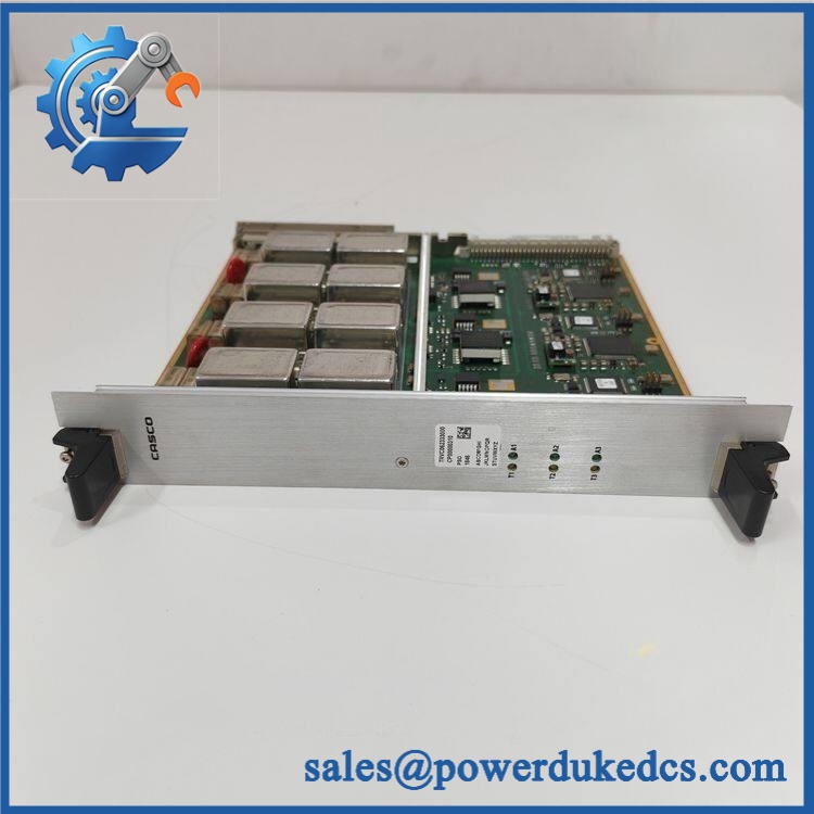
ALSTOM POS1846 TRVC062333000 CP00000310
Module 4: Application Scenarios & Field Realities
- During maintenance of an ALSTOM railway control cabinet, POS1846 should be treated as a configuration-specific electronic assembly. Record the complete TRVC062333000 and CP00000310 identifiers before removal so the replacement matches the installed hardware population.
- For vehicle or wayside equipment refurbishment, inspect the complete rack interface together with POS1846. An apparently healthy board can still report communication or initialization faults when the mating backplane connector has oxidation, mechanical wear, or insufficient contact pressure.
- When a control subsystem fails during commissioning, compare the board revision and configuration code before changing software. CP00000310 may represent a particular configured hardware population, so a board with the same family label is not automatically equivalent.
- During long-term spare-parts storage, protect this type of legacy controller board from moisture, ESD, contamination, and repeated connector handling. A clean power-on result after years of storage does not by itself prove reliable system-level operation.
Module 5: Migration, Compatibility & Installation Traps
Replacement Matrix
Replacement classification: Drop-in Replacement only when the existing installation specifically calls for TRVC062333000 and the replacement matches the board revision, firmware environment, chassis, connector arrangement, and system configuration.
Software compatibility: Configuration and firmware verification required. The exact role of should be preserved. Do not assume that a board with the same designation can be inserted without verifying firmware and host-system compatibility.
Cross-model replacement: Hardware modification or engineering verification required. Other ALSTOM controller boards may share similar rack dimensions or connector styles while using different processor architecture, address assignments, firmware, or I/O mappings.
Field Traps — Watch Out
1. Match all three identifiers. Procurement should reference + + rather than alone. The assembly and configuration codes provide important traceability for a legacy system.
2. Record board settings before removal. Photograph DIP switches, jumpers, address selectors, rotary switches, and any configurable links. These physical settings can determine how the board is recognized by the host controller.
3. Do not infer power requirements from another POS-series board. Until the exact ALSTOM documentation is available, use the existing cabinet drawing and nameplate as the electrical authority. Applying an assumed voltage to a processor board is not an acceptable bench-test method.
4. Verify the rack slot. A VME-style or proprietary rack board can be electrically keyed by its slot position, address, connector population, or backplane wiring. A board that physically fits a different position may still be electrically incompatible.
5. Preserve the existing firmware baseline. Before exchanging the board, record firmware or EPROM identifiers where accessible. A configuration mismatch can appear as a communication timeout or initialization failure even when the replacement hardware passes a standalone POST.
Module 6: Quality Assurance SOP
Pre-Shipment Inspection Protocol for ALSTOM
- OEM identity inspection: Verify ALSTOM marking, designation, identifier, configuration code, serial number, and revision information.
- Configuration inspection: Photograph the complete front and rear assembly and document every visible hardware identifier before testing.
- Mechanical inspection: Examine the PCB, enclosure, card guides, mounting hardware, backplane connector, front-panel components, and locking mechanism for cracks, deformation, corrosion, contamination, or unauthorized modification.
- Connector inspection: Check all board-edge or backplane contacts for oxidation, bent contacts, damaged plating, contamination, or mechanical wear.
- Component inspection: Inspect capacitors, regulators, processors, memory devices, sockets, connectors, and soldered joints for swelling, leakage, heat discoloration, cracking, or previous rework.
- Configuration-record check: Document DIP switches, jumpers, address selectors, EPROM labels, and any removable configuration devices before energization.
- Power verification: Confirm the correct supply voltage and polarity from the applicable ALSTOM equipment drawing or original documentation before applying power.
- Power-on self-test: Install the board in a verified compatible ALSTOM test chassis and monitor startup current, status indicators, reset behavior, and fault indications.
- Backplane handshake verification: Connect the board to the appropriate host controller or engineering fixture and verify expected initialization and backplane communication.
- Processor diagnostic test: Where the proper ALSTOM test environment is available, exercise processor, memory, watchdog, and internal diagnostic functions.
- Configuration verification: Confirm that -related configuration data or hardware identification is recognized correctly by the host system.
- Communication verification: Test the actual system communication interface used by the board rather than substituting a generic Ethernet or serial test.
- I/O or control-path verification: Where supported by the system fixture, exercise representative control transactions and confirm correct command/status exchange.
- Fault simulation: Introduce controlled communication, configuration, or power-cycle faults within the approved test procedure and verify appropriate diagnostic behavior.
- Extended operation test: Run the board under representative host traffic for an extended interval and monitor for resets, communication loss, watchdog events, or intermittent initialization failures.
- Thermal observation: Monitor critical processor, regulator, and power-conversion areas for abnormal temperature rise during sustained operation.
- Final QC record: Record , , , hardware revision, serial number, test chassis, supply conditions, startup results, communication results, diagnostic results, test duration, and inspector approval.
- ESD-controlled packaging: Place the board in an ESD-safe bag and protect connectors, PCB surfaces, mounting points, and configuration components against impact, vibration, moisture, contamination, and electrostatic discharge.
Procurement note: The safest technical description for ALSTOM is a configuration-specific ALSTOM railway control electronics assembly. Publicly accessible evidence is not sufficient to responsibly assign detailed processor, memory, voltage, protocol, or environmental specifications to this exact combination. For replacement purchasing, the complete + + identifier and the physical board revision should be treated as the primary matching criteria.











 Start Chat


