

Description
- Brand: Triconex / Invensys
- Full Model Number: 3601E
- System/Series Family: Tricon v9–v11
- Core Function: 16-point non-commoned, opto-isolated TMR digital output switching for 115 VAC field loads
- Top 3 Hardcore Specs: 16 output points; 80–155 VAC operating range; 2 A maximum per point
- Frequency Range: 47–63 Hz
- Surge Capability: 12 A per cycle
- Load Leakage: 2 mA maximum at 60 Hz
- Chassis Leakage: 4 mA maximum at 60 Hz
- On-State Voltage Drop: <2 VAC typical at 100 mA; <3 VAC maximum at 2 A at backplane
- Output Protection: 3 A fast-acting fuse per output on field termination
- Switching Technology: Zero-crossing TRIACs with inductive kick-back protection
- Isolation: 1,000 VAC minimum / 1,500 VDC minimum point isolation
- Diagnostics: Voltage-loopback output diagnostics
- Hot Spare: Supported
- Logic Power: <10 W
- Stock Status: New Surplus or Fully Tested Refurbished; exact revision to be confirmed
Tricon documentation identifies Model 3601E as a 16-point, opto-isolated TMR digital output module with a nominal 115 VAC rating. Its output points are non-commoned, and the module supports hot-spare operation through the Tricon architecture.
Module 3: Technical Product Introduction
A 115 VAC output circuit deserves more than a simple continuity check. The TRICONEX 3601E is a 16-point non-commoned TMR digital output module designed to source current to 115 VAC field devices. Each output is optically isolated, and the three internal channels participate in Tricon’s fault-tolerant output architecture. Tricon documentation specifies the module for a nominal 115 VAC field supply, with each point independently connected through the field termination arrangement.
The electrical limits are significant during replacement. The published operating range is 80–155 VAC at 47–63 Hz, with a maximum current of 2 A per point and a 12 A surge per cycle. Load leakage is limited to 2 mA at 60 Hz, while chassis leakage is limited to 4 mA. The module uses zero-crossing TRIAC outputs with reverse-EMF protection, and Tricon specifies point isolation of at least 1,000 VAC / 1,500 VDC for the 3601E. The associated field termination module carries one 3 A fast-acting fuse per output.
Module 4: Application Scenarios & Field Realities
- For 115 VAC contactors, solenoid interfaces, lamps, and other AC field loads, the 3601E provides 16 individually referenced output points. The non-commoned arrangement is useful where the field circuits require separate connections rather than a shared output return.
- During ESD or process shutdown cabinet maintenance, the module’s voltage-loopback diagnostics verify output-switch operation independently of the external load. A FAULT indication therefore needs to be investigated at the channel, termination, and field-load levels before the entire module is declared defective.
- Where an AC solenoid or contactor produces switching transients, the zero-crossing TRIAC design and reverse-EMF protection are relevant. Even so, field suppression, load type, inrush current, and the actual switching duty should be reviewed before assigning a 2 A output as a continuous load.
- For online maintenance programs, 3601E supports the Tricon hot-spare architecture and uses an external termination panel connected to the Tricon backplane. A replacement should therefore be qualified together with its termination hardware rather than tested as an isolated circuit board.
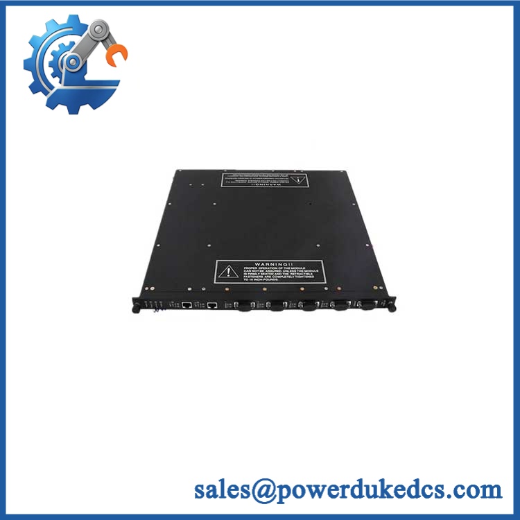
TRICONEX 3601E
Module 5: Migration, Compatibility & Installation Traps
Replacement Matrix
Replacement classification: Drop-in Replacement when the existing Tricon installation uses the same 3601E hardware, compatible termination panel, field-voltage arrangement, and supported system configuration.
Software compatibility: Configuration verification required. The module is an I/O device rather than a programmable CPU, but output assignments, diagnostic handling, active/spare configuration, and application logic must remain consistent with the existing Tricon system.
Cross-model replacement: Hardware and application verification required. The 3601E belongs to the 115 VAC TMR output family. Other Tricon output models use different field voltages, commoning arrangements, current ratings, or supervision methods and should not be substituted solely because they have 16 points.
Field Traps — Watch Out
1. Verify the AC field voltage at the termination panel. The specified operating range is 80–155 VAC. A nominal 115 VAC source that collapses during contactor pickup or passes through a high-resistance terminal may produce an unstable output condition.
2. Inspect the external fuse before replacing the module. The field termination module uses one 3 A fast-acting fuse per output. A blown fuse can interrupt the field load even when the 3601E output electronics are functioning correctly. Tricon also states that field power must be wired to each output point, including unused points on non-commoned panels.
3. Do not treat the 2 A rating as a universal load rating. The specification is 2 A per point with a 12 A surge/cycle capability, while the output is a TRIAC device. Contactors, solenoids, transformers, and other inductive loads can have current profiles very different from their steady-state nameplate values. Check inrush and suppression requirements before commissioning.
4. Distinguish 3601E from 3601T. Both are 115 VAC, 16-point TMR digital-output modules, but the 3601T has a higher point-isolation requirement. The 3601E is specified at 1,000 VAC minimum / 1,500 VDC minimum, while the 3601T is specified at 1,780 VAC minimum / 2,500 VDC minimum. They should therefore not be exchanged solely on nominal voltage and point count.
Module 6: Quality Assurance SOP
Pre-Shipment Inspection Protocol for TRICONEX 3601E
- OEM identity inspection: Verify Triconex/Invensys marking, exact 3601E designation, hardware revision, serial number, front-panel label, and additional assembly identifiers.
- Variant verification: Confirm the unit is 3601E, not 3601T or another 115 VAC Tricon digital-output variant.
- Mechanical inspection: Examine the housing, module guides, locking mechanism, card-edge/backplane interface, front-panel LEDs, PCB surfaces, and mounting features for corrosion, contamination, deformation, cracked components, or unauthorized repair.
- Connector inspection: Check the module and termination interfaces for oxidation, bent contacts, damaged housings, contamination, or loose hardware.
- Power-on self-test: Install the module in a compatible Tricon test chassis and verify PASS, FAULT, ACTIVE, individual point indications, and field-alarm behavior.
- 16-channel verification: Exercise all 16 output points independently. A single successful channel does not qualify the complete module.
- AC output test: Apply controlled 115 VAC field power and verify stable switching across representative points within the documented 80–155 VAC range.
- Frequency test: Where the test fixture permits, verify operation at representative 47–63 Hz AC conditions.
- Load test: Apply calibrated AC loads representing typical field devices and record output current, switching behavior, voltage drop, and thermal response.
- Current-limit verification: Test representative output loads below the 2 A per-point maximum and verify expected protective behavior under controlled conditions.
- Voltage-drop verification: Measure output-path voltage drop under representative loads and compare with the published limits, including the backplane and applicable external termination cable arrangement.
- Leakage verification: Measure Off-state load leakage and verify it remains within the documented 2 mA maximum at 60 Hz under the applicable test conditions.
- Field-fuse verification: Inspect all associated termination-panel fuses and verify the 3 A fast-acting specification, continuity, correct seating, and absence of thermal damage.
- Loopback diagnostic verification: Exercise the output voltage-loopback diagnostics and verify detection of representative output-switch faults.
- TMR verification: Where the laboratory system permits, validate the three internal output channels and confirm correct voted output behavior.
- Hot-spare test: Use an appropriate active/spare Tricon arrangement and verify module transfer according to the approved maintenance procedure.
- Thermal observation: Operate multiple AC outputs under representative loading for an extended interval and monitor for abnormal temperature rise, intermittent faults, excessive leakage, or output instability.
- Final QC record: Record exact model, revision, serial number, test chassis, supply voltage/frequency, all 16 output results, load values, voltage-drop measurements, leakage results, diagnostic results, fuse condition, hot-spare result where applicable, test duration, and inspector approval.
- ESD and mechanical packaging: Place the module in an ESD-safe package and protect the connectors, front-panel indicators, locking mechanism, and PCB surfaces from impact, moisture, contamination, and electrostatic discharge.
Procurement note: The technically supported identity is TRICONEX 3601E — Tricon 16-point, 115 VAC, non-commoned TMR Digital Output Module. The published specifications define 80–155 VAC operation, 47–63 Hz, 2 A maximum per point, 12 A surge per cycle, 2 mA maximum load leakage at 60 Hz, 3 A fast-acting field fuses, zero-crossing TRIAC outputs, voltage-loopback diagnostics, and 1,000 VAC / 1,500 VDC minimum point isolation. The termination assembly and field-power arrangement should be matched to the existing Tricon cabinet before approval.











 Start Chat


