

Description
- Brand Triconex / Invensys
- Full Model Number 3601T / Model 3601T
- System/Series Family Tricon Safety Instrumented System
- Core Function TMR digital output switching for 16 independent 115 VAC field loads
- Top 3 Hardcore Specs 16 non-commoned outputs | 80–155 VAC operating range | 2 A maximum per point
- Stock Status New Surplus — verify hardware revision, termination panel, field voltage, and load requirements before shipment
Module 3: Technical Product Introduction
A failed AC output can disable a motor starter, alarm circuit, solenoid interface, or other final control path even when the Tricon processors remain healthy. Triconex 3601T is a 16-point opto-isolated TMR digital output module designed for 115 VAC nominal field loads. The three processor channels independently provide output commands, after which fault-tolerant voting circuitry selects the field output. Triconex documentation identifies the 3601T as a 16-point, non-commoned output module with opto-isolated switching.
The electrical limits are specific. The published operating range is 80–155 VAC, with a 47–63 Hz frequency range. Each output supports up to 2 A, with a specified 12 A surge per cycle, while load leakage is limited to 2 mA maximum at 60 Hz. HIMA-style generic DC output assumptions do not apply here: the 3601T is an AC output design, and its field interface, termination protection, and isolation requirements must be matched to the installed Tricon architecture.
Module 4: Application Scenarios & Field Realities
- At a refinery shutdown cabinet, the 3601T can switch 115 VAC discrete loads such as relay coils, contactors, pilot devices, and other field circuits where AC output voltage is required. Its 16 non-commoned points allow separate output circuits rather than forcing several loads onto a shared return.
- Where final-element commands remain active for long periods, the TMR output architecture and continuous diagnostics are particularly important. Tricon documentation describes voltage-loopback circuitry that independently verifies each output switch and detects latent faults, while failure of a channel diagnostic activates the module fault indication.
- For high-inrush AC loads, the distinction between continuous point rating and surge capability matters. The documented figure is 2 A maximum per point with 12 A surge per cycle; a contactor or relay should therefore be evaluated for its actual inrush profile rather than its nominal steady-state current alone.
- During planned Tricon maintenance, the module supports the system’s hot-spare architecture, but the exact replacement sequence must follow the approved Tricon maintenance procedure. The external termination panel is part of the output circuit, so testing only the processor-side card does not establish complete field-circuit compatibility.
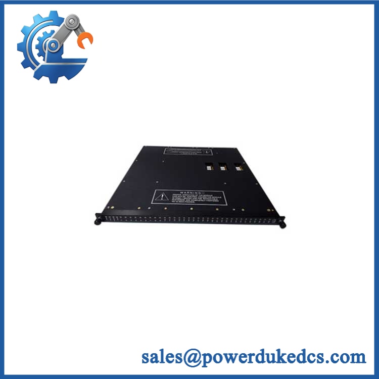
Triconex 3601T
Module 5: Migration, Compatibility & Installation Traps
Replacement Matrix
| Replacement Status | Engineering Assessment |
|---|---|
| Drop-in Replacement | Yes, for a like-for-like 3601T installation in a compatible Tricon chassis with the correct termination panel, field voltage, and approved hardware revision. |
| Software Compatible | Generally yes for an exact module replacement, but the configured output assignments, diagnostics, controller release, and approved Tricon database must be verified. |
| Hardware Modification Required | Normally no for an exact 3601T replacement. Hardware changes may be required when migrating to 3601E, 3603T, 3607E, or another output architecture. |
⚠️ Field Traps: Watch Out
Do not confuse 3601T with 3603T. Tricon documentation identifies 3601T as a 115 VAC output module and 3603T as a 120 VDC output module. Their voltage classes and field interfaces are different.
Check the field termination protection. The Tricon technical guide specifies one 3 A fast-acting fuse per output for the 3601T field termination. A blown fuse should trigger a field-load investigation rather than substitution with a higher-rated fuse.
Verify AC frequency and voltage together. The 3601T supports 80–155 VAC and 47–63 Hz. A nominal “120 VAC” test source is not sufficient evidence if the installed application operates outside the expected frequency or voltage envelope.
Do not interpret 2 A as unrestricted switching capability. The module is rated at 2 A maximum per point, with a specified 12 A surge per cycle. The actual load’s inrush, switching frequency, power factor, and suppression network should be reviewed before connecting an inductive AC device.
Respect non-commoned output wiring. Each output point has an independent field circuit. A wiring error that introduces an unintended common return can produce abnormal load behavior that is not caused by the processor module.
Module 6: Quality Assurance SOP
A surplus 3601T should be evaluated with both AC-load testing and TMR diagnostic verification. A simple continuity test does not prove that the output switches correctly under field conditions.
- OEM anti-counterfeit visual inspection: Verify Triconex/Invensys identification, exact 3601T designation, PCB revision, front-panel labels, green stripe, connector geometry, and visible manufacturing identifiers against controlled references.
- Part-number and traceability check: Record the complete module number, hardware revision, serial number, date code, and associated termination-panel information.
- Mechanical inspection: Examine the backplane connector, ejector hardware, PCB, enclosure, front-panel indicators, and mounting interfaces for bent contacts, corrosion, contamination, cracking, or unauthorized repair.
- Power-on self-test (POST): Install the module in an approved Tricon test chassis and verify expected PASS, FAULT, ACTIVE, and field/load status indications.
- AC supply verification: Apply a controlled 47–63 Hz AC source within the verified 80–155 VAC operating envelope and monitor module current and diagnostic behavior.
- 16-channel functional test: Exercise all 16 output channels independently and verify clean On/Off switching into controlled AC loads.
- Voltage-drop verification: Measure representative output voltage under load and compare it with the documented typical voltage-drop characteristic of less than 3 V, recognizing that application conditions can increase voltage drop.
- Current-load test: Test representative outputs at controlled current levels below the 2 A maximum point rating, monitoring switch temperature and output stability.
- Surge-load verification: Where the approved laboratory fixture permits, verify response to controlled inrush conditions consistent with the documented 12 A surge per cycle specification.
- Leakage test: Measure Off-state load leakage under the prescribed AC test conditions and verify it remains below the documented 2 mA maximum at 60 Hz.
- Output-isolation verification: Verify point isolation using the approved test procedure; the 3601T documentation specifies 1500 VDC / 2500 VDC isolation conditions for the applicable test configuration.
- Voltage-loopback diagnostic test: Execute the module’s output-switch verification procedure and confirm each output can be diagnosed independently, including controlled latent-fault simulations where authorized.
- Fuse-path verification: Confirm each field-output branch is associated with the appropriate 3 A fast-acting fuse in the termination assembly.
- TMR verification: Test the module in a complete three-channel configuration and confirm correct output voting and fault indication when one internal channel is subjected to an approved diagnostic fault.
- Baseplate and termination verification: Confirm correct mechanical mating, keying, cable connection, and field termination arrangement before applying production voltage.
- System recognition test: Verify correct module identification, output addressing, diagnostics, and state reporting through the Tricon I/O architecture.
- Communication handshake verification: Confirm successful output-command transfer between the Tricon processors and the 3601T, plus correct module diagnostic reporting. The 3601T is an I/O module rather than a standalone Ethernet or Modbus interface.
- Inductive-load test: Where appropriate, simulate a representative relay or contactor load and verify correct switching behavior with the approved suppression network.
- Extended-run test: Cycle representative channels under controlled AC loads while monitoring output stability, field-load current, diagnostic events, switch temperature, and intermittent faults.
- Final QC record: Document hardware revision, source voltage and frequency, all 16 output results, voltage drop, current measurements, leakage, isolation, fuse configuration, loopback diagnostics, TMR validation, extended-run observations, traceability, and packaging condition.
Technical Identification Note: The Triconex technical product guide identifies 3601E/3601T as 16-point, non-commoned, opto-isolated TMR digital output modules with a nominal 115 VAC output. The published 3601T characteristics include 80–155 VAC, 47–63 Hz, 2 A maximum per point, 12 A surge per cycle, 2 mA maximum load leakage at 60 Hz, and a higher point-isolation minimum specifically noted for the 3601T.











 Start Chat


