

Description
- Brand: TRICONEX
- Full Model Number: 3603E
- System/Series Family: Tricon v9–v11 TMR safety system
- Core Function: 16-channel TMR digital output module for high-voltage DC field loads
- Top 3 Hardcore Specs: 16 commoned outputs; 120 VDC nominal; 90–150 VDC operating range
- Stock Status: Verify current New Surplus, Factory Sealed, or Fully Tested Refurbished condition before order
Module 3: Technical Product Introduction
A failed high-voltage output card can remove multiple shutdown commands, solenoid controls, or actuator signals from a Tricon safety controller. TRICONEX 3603E is a 16-point TMR digital output module designed for nominal 120 VDC field circuits. Triconex documentation specifies 16 commoned output signals, a 90–150 VDC operating range, and a 160 VDC maximum input to the field-output circuitry. The module receives three corresponding output signals from the Main Processors, applies TMR voting through redundant output circuitry, and drives the voted field signal through the external termination assembly.
The electrical limits must be matched to the load. Each 3603E output is rated at 0.8 A continuous with a 4 A surge capability for 10 ms, while load leakage is limited to 2 mA and the specified field-termination fuse is 1 A fast-acting per output. Minimum point isolation is 1,500 VDC. Triconex also specifies voltage-loopback diagnostics that verify output-switch operation independently of the field load and raise the LOAD/FUSE indication when the sensed field voltage does not agree with the commanded state.
Module 4: Application Scenarios & Field Realities
- Inside a Tricon cabinet controlling 120 VDC shutdown devices, the 3603E provides 16 commoned output points for field loads such as DC solenoids, relays, contactor interfaces, or other discrete actuators. The commoned architecture must match the termination-panel wiring used by the installation.
- When a shutdown output must remain energized for extended periods, the module’s continuous diagnostics become important. Triconex uses output voltage-loopback circuitry to check each output switch even without depending solely on the connected load; a mismatch between commanded and sensed field voltage can activate the LOAD/FUSE indication.
- During brownfield replacement of a 3603E, verify the actual field voltage before installation. The nominal system value is 120 VDC, with a documented operating range of 90–150 VDC. A 48 VDC or 24 VDC output module from the same Tricon family is not electrically equivalent simply because it provides 16 digital outputs.
- For long field cables or unusual loads, cable and load characteristics can affect the output diagnostic circuit. Triconex specifically recommends compatibility testing for related 3603-series configurations when field wiring exceeds 100 meters, when cable construction differs from twisted pair, or when loads include devices such as smart electronics, strobes, or klaxons.
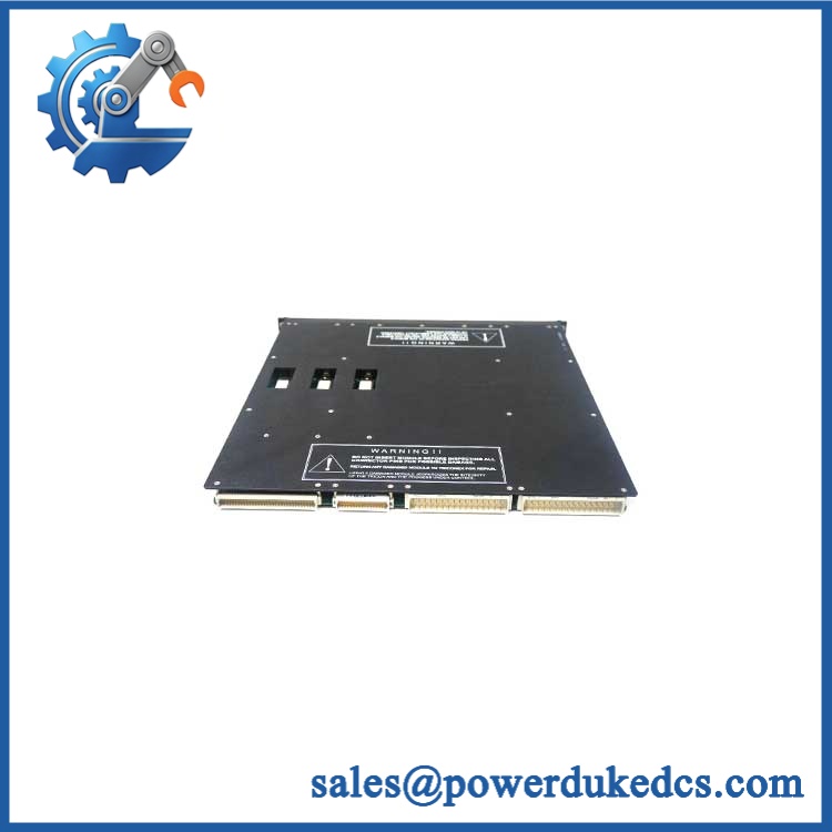
TRICONEX 3603E
Module 5: Migration, Compatibility & Installation Traps
Replacement Matrix
Exact 3603E with matching Tricon configuration: Drop-in Replacement
When the installed controller uses 3603E with the correct external termination panel, 120 VDC field supply, compatible chassis, and approved system configuration, replacement is normally a direct hardware exchange.
3603E hardware revision change: Software Compatible / Configuration Verification Required
Record the installed module revision and project configuration before replacement. Verify output assignments, diagnostics, and controller compatibility after installing the spare.
3603B or 3603T substituted for 3603E: Hardware Modification Required unless specifically approved
The 3603-series variants are related but not interchangeable by default. Triconex documentation explicitly warns that 3603B, 3603E, and 3603T should not be mixed in the same logical slot. The 3603E is the commoned-output version, while 3603B uses non-commoned outputs; 3603T has different isolation characteristics.
3607E or 3604E substituted for 3603E: Hardware Modification Required
These modules operate at different nominal field voltages—48 VDC for 3607E and 24 VDC for 3604E—so they are not direct electrical replacements for a 120 VDC 3603E.
⚠️ Field Traps (Watch Out)
Commoned-output trap: The 3603E has 16 commoned outputs. The 3603B, by contrast, is the non-commoned configuration. If the existing field design requires independently separated returns, moving from one configuration to the other is not a simple module swap.
Voltage trap: The documented operating range is 90–150 VDC, with a maximum of 160 VDC. Do not apply a 24 VDC or 48 VDC field supply and expect normal operation; conversely, do not place a lower-voltage output card into a 120 VDC circuit.
Logical-slot trap: Triconex specifically states that 3603B, 3603E, and 3603T must not be mixed within the same logical slot. Confirm the slot’s configured module type before inserting a replacement.
Load/fuse diagnostic trap: The LOAD/FUSE alarm does not automatically mean the entire module has failed. Triconex documentation states that the indication can result when the detected field voltage does not match the commanded output state; inspect the field fuse, wiring, load, and termination assembly before replacing the module.
Module 6: Quality Assurance SOP
Pre-Shipment QA Protocol for TRICONEX 3603E
- Step 1 — Identity Verification: Confirm TRICONEX marking, 3603E model number, serial number, hardware revision, manufacturing information, and associated field-termination identification.
- Step 2 — OEM Anti-Counterfeit Visual Inspection: Inspect labels, barcodes, PCB markings where accessible, connector geometry, mechanical keying, front-panel indicators, retaining hardware, and evidence of unauthorized modification.
- Step 3 — Mechanical Inspection: Check the housing, card-edge connector, alignment features, retaining hardware, field connector interface, and enclosure for cracks, corrosion, contamination, or deformation.
- Step 4 — Test Fixture Verification: Prepare an isolated DC output test system capable of safely handling the documented 90–150 VDC operating range and the specified output-current conditions.
- Step 5 — Power-On Self-Test: Install the module in an approved Tricon test chassis and verify normal startup, PASS/FAULT/ACTIVE status indications, and absence of module diagnostics.
- Step 6 — 16-Channel Output Test: Exercise all 16 channels individually with controlled loads. Record commanded state, measured field voltage, output current, and front-panel channel indication.
- Step 7 — Current and Surge Verification: Test representative output channels at controlled load levels while remaining within the documented 0.8 A per-point continuous rating and approved test-fixture limits.
- Step 8 — Loopback Diagnostic Verification: Confirm correct voltage-loopback behavior and verify the LOAD/FUSE diagnostic response using a controlled field-fault simulation.
- Step 9 — TMR Output Verification: Confirm that the three processor-originated output paths participate correctly in the approved TMR test configuration and that no unexplained voter or channel diagnostics are generated.
- Step 10 — Final QC Record: Record model, serial number, hardware revision, all 16 channel results, output voltage, load current, diagnostic results, visual condition, test date, and final QC disposition.
Technical Verification Note: Triconex documentation identifies 3603E as a TMR 16-point digital output module with 120 VDC nominal field voltage, 90–150 VDC operating range, 0.8 A maximum per point, 4 A surge for 10 ms, 2 mA maximum load leakage, and 1,500 VDC minimum point isolation. The outputs are commoned, and the module uses voltage-loopback diagnostics with PASS/FAULT/ACTIVE and LOAD/FUSE indications.











 Start Chat


