

Description
- Brand: TRICONEX
- Full Model Number: 3604E
- System/Series Family: Tricon v9–v11 TMR I/O System
- One-Sentence Core Function: 16-point non-commoned opto-isolated TMR digital output module for 24 VDC field loads
- Top 3 Hardcore Specs: 16 outputs; 22–45 VDC operating range; 2 A maximum per point
- Stock Status: New Surplus / Fully Tested Refurbished — verify termination panel, field supply, and Tricon revision before shipment
Module 3: Technical Product Introduction
When a safety command reaches the logic layer but the final field actuator does not respond, the digital-output stage becomes the first hardware point to investigate. The TRICONEX 3604E is a 16-point TMR digital output module for Tricon systems, designed for nominal 24 VDC field loads. Tricon technical documentation classifies it as opto-isolated, non-commoned, TMR, with one output status indicator per point and module-level PASS, FAULT, and ACTIVE indications.
The electrical limits are specific enough to matter during replacement. The documented field voltage range is 22–45 VDC, with a maximum output current of 2 A per point and a 10 A surge for 10 ms. Output leakage is limited to 2 mA maximum, point isolation is specified at 1,500 VDC minimum, and each field termination uses a 2.5 A fast-acting fuse. The module also incorporates voltage loopback diagnostics to determine whether the actual field voltage agrees with the commanded output state.
Module 4: Application Scenarios & Field Realities
- At shutdown valves, solenoid-operated devices, and other 24 VDC final elements, the 3604E provides the Tricon-side switching function. Because the outputs are non-commoned, each point has its own field supply path rather than sharing a common output terminal arrangement.
- When an actuator remains de-energized even though the control program commands ON, check the field supply, termination fuse, cable, and load before replacing the module. The 3604E’s voltage-loopback circuitry can indicate a mismatch between the commanded state and actual field voltage.
- For high-current discrete loads, do not size the application from the 2 A figure alone. The published limit is 2 A per point, with a defined 10 A surge for 10 ms; coil inrush, suppression, wiring resistance, and the actual termination arrangement still have to be evaluated.
- During brownfield cabinet replacement, the field termination module deserves the same attention as the electronic board. Tricon documentation states that TMR digital-output modules use separate external termination panels and cable interfaces, and the compatible 9653-610 termination panel is specifically documented for the 3604E.
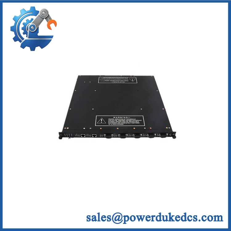
TRICONEX 3604E
Module 5: Migration, Compatibility & Installation Traps
Replacement Matrix
| Replacement Type | Assessment |
|---|---|
| Drop-in Replacement | Yes, for an exact 3604E replacement in a compatible Tricon I/O configuration |
| Software Compatible | Conditional — verify Tricon system revision, I/O database, channel assignments, and diagnostic configuration |
| Hardware Modification Required | Normally no for an exact replacement; termination panel, field supply, fuse arrangement, and load characteristics must match |
⚠️ Field Traps — Watch Out
1. Do not substitute another 36xx output module based only on voltage.
The 3604E is a 24 VDC, 16-point, non-commoned TMR output module. For example, 3607E is also a 16-point TMR output module but is designed for 48 VDC service.
2. Check the field termination fuse.
The 3604E termination arrangement uses one 2.5 A fast-acting fuse per output. A field fuse that repeatedly opens can indicate a load or wiring problem; simply replacing the fuse without checking the field circuit can cause repeat failures.
3. Keep unused points supplied as specified.
Tricon documentation notes that power must be supplied to all output points, including unused points on applicable non-commoned termination panels. A missing field supply can therefore create a diagnostic condition that is mistaken for a bad channel.
4. Verify the actual termination panel.
The 9653-610 termination panel is explicitly listed as compatible with the 3604E. Do not assume a neighboring Tricon output termination panel is equivalent simply because the cable connector fits.
Module 6: Quality Assurance SOP
- OEM anti-counterfeit visual inspection — inspect TRICONEX identification, 3604E marking, module label, housing, status indicators, locking hardware, connector interfaces, and visible manufacturing details.
- Exact part-number verification — confirm 3604E against the purchase order, physical label, and inventory record.
- System-family verification — confirm the intended installation is a compatible Tricon v9–v11 architecture and identify the installed I/O termination arrangement.
- Termination verification — verify the field termination panel and cable. For the documented arrangement, 9653-610 is listed as compatible with 3604E.
- Mechanical inspection — inspect the backplane connector, field-interface connector, locking features, PCB surfaces, housing, and mounting hardware for bent contacts, contamination, corrosion, cracks, or impact damage.
- Power-on self-test (POST) — energize the module in an approved Tricon test chassis and record PASS, FAULT, and ACTIVE indications, current behavior, and abnormal temperature rise.
- 16-channel output simulation — operate representative output points into controlled loads and verify commanded ON/OFF switching at the appropriate 24 VDC test supply.
- Full-channel verification — where the test fixture permits, exercise all 16 outputs individually and record commanded state, measured voltage, load current, and diagnostic status.
- Loopback verification — verify the voltage-loopback function on representative channels by comparing commanded output state with measured field voltage. The Tricon architecture uses this function to detect latent output-switch faults.
- Current and surge validation — where the approved test fixture supports it safely, verify operation against the documented 2 A per-point maximum and controlled 10 A/10 ms surge behavior without creating an uncontrolled short-circuit condition.
- Field-fuse verification — confirm the applicable termination uses the specified 2.5 A fast-acting fuse per output and verify fuse-monitoring behavior under controlled test conditions.
- TMR verification — install the tested module with compatible Tricon processors and verify correct triplicated output processing, module diagnostics, and field-output behavior.
- Communication handshake verification — verify I/O communication through the complete Tricon controller architecture. This is a system-level test rather than a direct Ethernet or serial-port test.
- Fault simulation — use an approved test fixture to simulate permissible field-power, fuse, or load conditions and confirm the expected LOAD/FUSE diagnostic response.
- Final QC and packaging — record model number, hardware revision, 16-channel test results, loopback verification, termination-panel reference, photographs, ESD protection, and packaging condition before shipment.
Engineering note: The TRICONEX 3604E is documented as a 16-point, 24 VDC, non-commoned, opto-isolated TMR digital-output module for Tricon systems. Its specified operating range is 22–45 VDC, with 2 A maximum per point, 10 A surge for 10 ms, 2 mA maximum load leakage, and 1,500 VDC minimum point isolation. The corresponding field termination uses one 2.5 A fast-acting fuse per output, and Tricon documentation lists 9653-610 as a compatible termination panel.











 Start Chat


