

Description
-
- Brand: TRICONEX / Invensys
- Full Model Number: 3607E
- System/Series Family: Tricon v9–v11
- One-Sentence Core Function: 16-point TMR digital output module for 48 VDC field loads and safety-related actuator commands
- Top 3 Hardcore Specs: 16 non-commoned outputs; 44–80 VDC operating range; 1 A per point with 5 A surge for 10 ms
- Stock Status: Stock condition and hardware revision to be confirmed
Module 3: Technical Product Introduction
When a high-voltage DC actuator stops responding, the output module, termination hardware, field supply, and load circuit all need to be checked separately. TRICONEX 3607E is a 16-point TMR digital output module for Tricon v9–v11 systems, designed for nominal 48 VDC field service. The 16 outputs are non-commoned, each point has individual status indication, and triplicated processing supports the Tricon fault-tolerant architecture. Hot-spare operation is also supported within the applicable Tricon configuration.
Its electrical limits leave little room for guesswork. The specified field-voltage range is 44–80 VDC, with 1 A continuous output current per point and a 5 A surge rating for 10 ms. Point isolation is rated at 1,500 VDC minimum. Logic power consumption is below 10 W, while the output voltage drop depends on load current and termination arrangement; at 1 A, the published external-termination case allows up to 7 VDC of total drop. That makes field-cable resistance and actuator burden part of the replacement calculation, not an afterthought.
Module 4: Application Scenarios & Field Realities
- For 48 VDC solenoids and shutdown actuators, the 3607E provides the discrete command path from the Tricon controller to the final element. Compare the actual coil current with the 1 A channel rating, including startup behavior and any protective components installed across the load.
- In turbine and compressor protection cabinets, the 16 outputs can serve independent field circuits because the outputs are non-commoned. Each circuit should be checked individually at the termination point; a shared-return assumption can produce a wiring error even when the module itself is correct.
- Where field wiring runs are long, voltage-drop calculations become critical. At 1 A, the documented external-termination voltage drop can reach 7 VDC. Measure the available voltage at the actuator, not just at the Tricon rack, especially when cable runs include marshalling terminals or additional interface devices.
- During online spare replacement, the hot-spare capability can reduce maintenance disruption, but the approved Tricon procedure still controls the sequence. Capture the existing module status and diagnostic condition before removal so a separate field fault is not mistaken for a replacement-module problem.
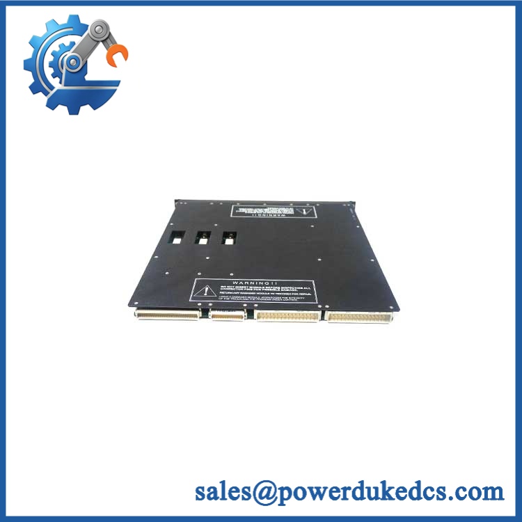
TRICONEX 3607E
Module 5: Migration, Compatibility & Installation Traps
Replacement Matrix
Replacement Classification: Drop-in Replacement Within the Matching Tricon 3607E Configuration
A like-for-like 3607E replacement is appropriate when the existing Tricon installation uses the same 48 VDC TMR digital-output architecture, compatible chassis and termination hardware, and matching application configuration. The 3607E is a specific member of the Tricon digital-output family and should be replaced with the same electrical class unless an approved engineering change has been completed.
3607E → 3604E: Hardware Modification Required. The 3604E is designed for nominal 24 VDC service, while the 3607E is the 48 VDC version. Their field-power arrangements and electrical operating ranges are different.
3607E → 3603E / 3603T: Hardware Modification Required. These models are associated with substantially higher DC field-voltage applications. They cannot be treated as drop-in substitutes for a 48 VDC 3607E circuit.
⚠️ Field Traps — Watch Out
1. Field-voltage mismatch: The 3607E is specified for 44–80 VDC. A 24 VDC or 120 VDC output module may have a similar physical role but is not an electrical substitute.
2. Cable voltage drop: With external termination, the documented drop can reach 7 VDC at 1 A. For high-current solenoids, calculate voltage from the supply through the output electronics, termination, cable, and final element.
3. Diagnostic pulse behavior: Output diagnostics can create a brief test pulse. The published duration is approximately 500 µs typical and 2 ms maximum. Check the connected actuator or interposing relay to ensure the diagnostic activity cannot be interpreted as an unintended command.
4. Non-commoned field arrangement: The outputs are individually configured rather than sharing one common output return. Confirm the termination wiring point by point before applying field power.
Module 6: Quality Assurance SOP
Each TRICONEX 3607E should undergo a documented identification, electrical, diagnostic, and TMR functional test sequence before shipment.
- OEM identification visual inspection: Verify TRICONEX / Invensys markings, 3607E designation, serial number, hardware revision, front-panel labeling, connectors, ejector hardware, and status indicators.
- Architecture verification: Confirm the customer application requires a 48 VDC TMR digital output module and identify the corresponding Tricon chassis and termination arrangement.
- Mechanical inspection: Examine the enclosure, PCB, connector interface, ejectors, guide/keying features, LEDs, and mounting surfaces for impact, corrosion, contamination, or evidence of repair.
- Power verification: Install the module in an approved Tricon test chassis and verify operation using a controlled field supply within the documented 44–80 VDC range.
- Power-on self-test (POST): Confirm normal initialization and expected Pass, Fault, and Active indications.
- 16-channel output test: Exercise all 16 outputs independently using a controlled 48 VDC load fixture and record commanded state, measured voltage, and load current.
- Current-load verification: Test representative outputs below the 1 A per-point continuous limit and verify stable operation under approved transient conditions.
- Voltage-drop test: Measure representative output voltage at controlled loads and document the relationship between supply voltage, output current, termination arrangement, and load-side voltage.
- Isolation verification: Where authorized, verify the specified 1,500 VDC minimum point-isolation characteristic using appropriate test equipment and protection procedures.
- Diagnostic verification: Exercise the approved output diagnostic routine and confirm the expected fault detection and status reporting.
- TMR verification: Confirm that all three processing paths participate correctly in the output architecture and that the voted result is consistent.
- Hot-spare verification: Where required, place the module in an approved standby arrangement and verify module recognition and controlled changeover behavior.
- Inductive-load test: For solenoid or relay applications, use an approved representative inductive load and verify correct switching behavior and protective response.
- Extended stability test: Cycle representative outputs continuously while monitoring output current, voltage drop, diagnostics, TMR communication, and thermal behavior.
- Final QC record: Retain complete part-number photographs, hardware revision, termination reference, all 16 output results, load conditions, voltage-drop measurements, diagnostic results, TMR verification, hot-spare results, and final QC approval.
The TRICONEX 3607E is a 16-point TMR digital output module for nominal 48 VDC service, with 44–80 VDC operation, 1 A per output, 5 A surge for 10 ms, non-commoned outputs, minimum 1,500 VDC point isolation, and integrated output diagnostics.
For spare-parts control, the decisive checks are the 48 VDC field architecture, compatible termination hardware, actuator load, cable voltage drop, diagnostic behavior, and Tricon v9–v11 system compatibility. A visually similar 24 VDC or higher-voltage output module should not be released as a direct replacement without an approved engineering review.











 Start Chat


