

Description
- Brand: TRICONEX
- Full Model Number: 3624
- System/Series Family: Tricon v9–v11 TMR safety system
- Core Function: 16-channel supervised digital output interface for monitored 24 VDC field loads
- Top 3 Hardcore Specs: 16 commoned outputs; 16–30 VDC operating range; 0.7 A/point with 4.8 A surge for 10 ms
- Stock Status: Verify current New Surplus, Factory Sealed, or Fully Tested Refurbished condition before order
Module 3: Technical Product Introduction
An energized output is not necessarily a healthy output circuit. A field fuse can open, a solenoid can disconnect, or wiring can short while the controller continues to issue the same command. The TRICONEX 3624 is a 16-point TMR Supervised Digital Output (SDO) module designed for 24 VDC field circuits. Triconex technical documentation specifies 16 commoned outputs, optical isolation, self-protection, and diagnostic supervision intended to detect field-side conditions rather than merely report the commanded output state.
The field-side specification is tightly defined: 16–30 VDC recommended operating voltage, 36 VDC maximum, 0.7 A maximum per output, and 4.8 A surge capability for 10 ms. Each point requires a minimum 30 mA load, while load leakage is limited to 4 mA. The output circuitry is self-protected against over-voltage, over-temperature, and over-current, and Triconex specifies a minimum 1,500 VDC point isolation. Diagnostic checking runs at up to every 100 ms plus one system scan.
Module 4: Application Scenarios & Field Realities
- In shutdown and fire-and-gas cabinets, the 3624 is appropriate when a field output must be supervised instead of treated as a simple ON/OFF command. The diagnostic architecture can identify conditions such as loss of field power, open or missing load, and certain field shorts.
- When controlling solenoids, relays, or other 24 VDC actuators, the 30 mA minimum load becomes a practical commissioning check. A very-low-current electronic load may not behave like the field device for which the supervision circuit was engineered.
- For brownfield Tricon installations, the commoned-output architecture must match the termination panel. Triconex documentation identifies the 9662-610 family as a compatible commoned 24 VDC termination solution, while other termination arrangements are used for basic, nonincendive, or fanned-out installations.
- During long-term energized service, supervision is particularly useful because the 3624 is intended for outputs that may remain in one state for extended periods. The diagnostic system checks the output circuitry and field circuit without requiring operators to repeatedly toggle the process device.
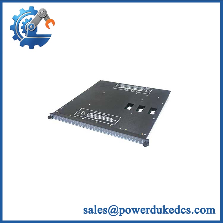
TRICONEX 3624
Module 5: Migration, Compatibility & Installation Traps
Replacement Matrix
Exact 3624 with matching Tricon configuration: Drop-in Replacement
When the installed system uses Model 3624, the correct external termination hardware, 24 VDC field supply, compatible controller configuration, and matching field wiring, the module can normally be replaced as a like-for-like hardware exchange.
3624 hardware or termination revision change: Software Compatible / Hardware Verification Required
Verify the controller version, module revision, termination assembly, field common arrangement, and configured output assignments before releasing the replacement.
3625 substituted for 3624: Hardware Modification Required
Both belong to the supervised-output family, but 3625 provides 32 commoned outputs and has different electrical and termination requirements. A 3625 is not a direct 16-point replacement.
3604E substituted for 3624: Hardware Modification Required
3604E is a 24 VDC TMR digital-output module, but it is non-commoned and not the same supervised-output architecture. The field termination and diagnostic requirements therefore differ.
⚠️ Field Traps (Watch Out)
Supervision-load trap: The 3624 requires a minimum 30 mA field load. An actuator or test load drawing substantially less current can generate a missing-load diagnostic even when the output circuit is electrically functional.
Commoned-output trap: The 16 outputs are commoned, so the field-return architecture must be compatible with the selected termination panel. Do not assume the 3624 provides 16 individually isolated output returns merely because each channel has diagnostic supervision.
Voltage-drop trap: Published documentation shows output voltage drop increasing with cable length and load current. With external termination and a 99-foot cable, the specified drop can reach 6.0 VDC maximum at 1 A. Long field runs therefore require an actual loop-voltage calculation rather than a nominal 24 V assumption.
Termination trap: The 3624 requires an external termination arrangement. Triconex documentation lists 9662-610 for commoned 24 VDC termination and 9653-610 for the basic arrangement. Verify the exact termination assembly before connecting field wiring.
Module 6: Quality Assurance SOP
Pre-Shipment QA Protocol for TRICONEX 3624
- Step 1 — Identity Verification: Confirm TRICONEX marking, Model 3624, serial number, hardware revision, manufacturing information, and associated termination-panel identification.
- Step 2 — OEM Anti-Counterfeit Visual Inspection: Inspect labels, barcodes, PCB markings where accessible, connector geometry, mechanical keys, front-panel indicators, retaining hardware, and evidence of unauthorized component replacement.
- Step 3 — Mechanical Inspection: Check the module housing, card-edge connector, field interface, alignment features, retaining hardware, and enclosure for cracks, deformation, corrosion, contamination, or damaged contacts.
- Step 4 — Test Fixture Verification: Prepare an isolated 24 VDC output test fixture with representative loads meeting the documented minimum 30 mA requirement.
- Step 5 — Power-On Self-Test: Install the module in an approved Tricon test chassis and verify normal startup, PASS/FAULT/ACTIVE status, and absence of module diagnostics.
- Step 6 — 16-Channel Output Test: Exercise all 16 channels individually. Record commanded state, measured field voltage, load current, output indication, and diagnostic status.
- Step 7 — Supervision Test: Simulate approved open-load, missing-load, field-power-loss, and short-circuit conditions individually. Verify the expected Power/Load diagnostic response without exposing the production circuit to uncontrolled faults.
- Step 8 — Self-Protection Test: Under controlled laboratory conditions, verify representative over-current behavior and confirm that the output returns to the expected safe state after removal of the simulated fault.
- Step 9 — TMR Diagnostic Verification: Confirm correct operation of the three redundant output-processing paths and verify that no unexplained voter, channel, or field diagnostic is generated during stable test conditions.
- Step 10 — Final QC Record: Record model, serial number, hardware revision, all 16 channel results, load current, output voltage, supervision results, diagnostic status, visual condition, test date, and final QC disposition.
Technical Verification Note: Triconex documentation identifies 3624 as a TMR Supervised Digital Output module with 16 commoned 24 VDC outputs. The documented recommended voltage range is 16–30 VDC, maximum voltage 36 VDC, maximum output current 0.7 A per point, surge capability 4.8 A for 10 ms, minimum load 30 mA, maximum load leakage 4 mA, and minimum point isolation 1,500 VDC. The module is self-protected and provides field supervision for conditions including loss of field power, open/missing loads, and field shorts.











 Start Chat


