Description
- Brand: TRICONEX
- Full Model Number: 3625A
- System/Series Family: Tricon v10.2 and later TMR I/O
- One-Sentence Core Function: 32-point TMR supervised or non-supervised digital output module for 24 VDC field loads
- Top 3 Hardcore Specs: 32 commoned outputs; 16–32 VDC recommended range; 1.7 A ±10% maximum per point
- Stock Status: New Surplus / Fully Tested Refurbished — verify termination-panel arrangement and Tricon system revision before shipment
Module 3: Technical Product Introduction
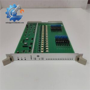
When a Tricon output must remain energized or de-energized for long periods, ordinary output diagnostics may not provide enough fault coverage. The TRICONEX 3625A is a 32-point TMR supervised or non-supervised digital output module designed for 24 VDC nominal field service in Tricon v10.2 and later systems. Its output architecture supports both energize-to-trip and de-energize-to-trip applications, while voltage and current loopback circuitry provides diagnostic coverage of output and field-circuit conditions.
The key architectural change from the 3625 is the field-power distribution. The 3625A separates field power into two groups of 16 points while retaining a common return, whereas the original 3625 has field power commoned across all 32 points. The published specifications call for a 16–32 VDC recommended range, 36 VDC maximum, 1.70 A ±10% maximum per point, 5 A surge for 7 ms, and 10 A total module output current per termination panel. Output leakage is limited to 2.0 mA at 24 VDC and 2.5 mA at 32 VDC.
Module 4: Application Scenarios & Field Realities
- At shutdown valves, solenoids, and other 24 VDC final elements, the 3625A provides a triplicated output path while allowing the field supply to be divided into two 16-point groups. This is useful when independent power feeds are required across portions of a 32-point output arrangement.
- For outputs that remain in one state for extended periods, the supervised configuration adds an important diagnostic layer. The Tricon architecture uses voltage and current loopback circuitry to detect output-switch, field-circuit, and load-related problems without deliberately disturbing the commanded output.
- During brownfield replacement of a 3625, the 3625A is especially useful because the technical guide states that it is fully compatible with applications of the 3625. The field-power topology changes, however, so the existing termination-panel wiring must be reviewed before treating it as a simple board exchange.
- Where multiple field power sources are considered, follow the documented voltage-matching requirement carefully. The 3625A can use four independent field-power sources only when their voltages remain within 5% of the highest supplied voltage; otherwise, voter faults and alarms can occur even though the module continues to operate.
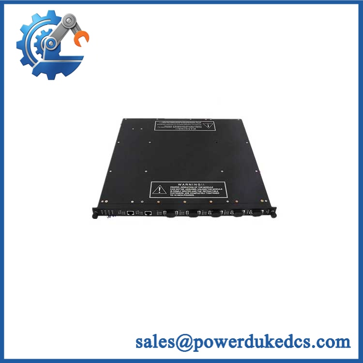
TRICONEX 3625A
Module 5: Migration, Compatibility & Installation Traps
Replacement Matrix
| Replacement Type | Assessment |
|---|---|
| Drop-in Replacement | Yes, for a like-for-like 3625A installation; also suitable as a documented functional replacement for 3625 applications when the field-power topology is reviewed |
| Software Compatible | Conditional — verify Tricon v10.2+ compatibility, point supervision settings, I/O configuration, and application database |
| Hardware Modification Required | Normally no for a 3625A-to-3625A replacement; termination panels and field-power grouping must match |
⚠️ Field Traps — Watch Out
1. The field-power topology is different from 3625.
The 3625A divides field power into groups of 16 points while maintaining a common return. This is the defining hardware change from the original 3625 and must be reflected in the termination-panel wiring.
2. Do not mix independent field supplies without checking voltage matching.
The technical guide permits four independent field supplies only when their voltages are within 5% of the highest supplied voltage. A mismatch can create voter faults and alarms.
3. Respect the minimum OFF-state load.
The documented minimum required load is 10 mA within 100 μs for an OFF point. Very low-current electronic loads may therefore require a properly engineered interface rather than direct connection.
4. Supervised and non-supervised operation are configuration-dependent.
The 3625A supports both modes. Point supervision can be programmed per point, and short/open-circuit detection thresholds are programmable for supervised points. Confirm the existing application configuration before commissioning.
Module 6: Quality Assurance SOP
- OEM anti-counterfeit visual inspection — inspect TRICONEX identification, 3625A model marking, dark-blue stripe, status indicators, connectors, housing, and manufacturing labels.
- Exact part-number verification — confirm 3625A against the purchase order and physical module label.
- System-family verification — confirm that the target installation is Tricon v10.2 or later, the documented minimum system revision for the 3625/3625A family.
- Termination verification — confirm the 16-point commoned termination-panel arrangement and verify that field power is correctly divided for the 3625A’s two 16-point groups.
- Mechanical inspection — examine backplane connectors, field interfaces, locking hardware, PCB surfaces, housing, and mounting features for corrosion, bent contacts, cracks, contamination, or impact damage.
- Power-on self-test (POST) — energize the module in an approved Tricon test chassis and record PASS, FAULT, ACTIVE, and LOAD status indications, supply behavior, current draw, and abnormal temperature rise.
- 32-channel output simulation — drive representative outputs into controlled test loads and verify correct ON/OFF switching at the appropriate 24 VDC test conditions.
- Full-channel verification — where the fixture permits, exercise all 32 output points individually and record commanded state, field voltage, load current, loopback status, and diagnostic result.
- Output protection verification — validate the self-protection behavior under controlled test conditions. The documented output switches protect against over-voltage, over-temperature, over-current, and reverse EMF.
- Load and current validation — verify representative channels against the 1.70 A ±10% maximum per-point rating, while checking that total output demand remains within the documented 10 A per termination panel limit.
- Loopback verification — test voltage and current loopback on representative channels and confirm that the diagnostic system correctly identifies simulated field/output faults.
- Supervision verification — where the application is configured for supervised operation, simulate approved open- and short-circuit conditions and verify the programmed diagnostic response.
- Field-power grouping verification — confirm that the two 16-point power groups are supplied correctly. For installations using multiple independent supplies, verify the required voltage matching before energization.
- TMR verification — install the tested module with compatible Tricon processor and I/O hardware and verify triplicated output processing, diagnostics, and stable module operation.
- Communication handshake verification — verify I/O communication through the complete Tricon architecture. This is a system-level verification rather than a direct Ethernet or serial-port test.
- Final QC and packaging — document model number, hardware revision, 32-channel results, supervision status, field-power arrangement, diagnostic results, photographs, ESD protection, and packaging condition.
Engineering note: The TRICONEX 3625A is documented as a 32-point TMR supervised or non-supervised digital output module for Tricon v10.2 and later systems. It operates at 24 VDC nominal, with a 16–32 VDC recommended range, 36 VDC maximum, and 1.70 A ±10% maximum per point. Its defining difference from the 3625 is the division of field power into two groups of 16 points, while the 3625A remains functionally compatible with 3625 applications.