

Description
- Brand: TRICONEX / Invensys
- Full Model Number: 3625C1
- System/Series Family: Tricon v9–v11
- One-Sentence Core Function: 32-point TMR digital output module for 24 VDC field loads with supervised and non-supervised operating modes
- Top 3 Hardcore Specs: 32 commoned outputs; 16–32 VDC operating range; 1.7 A per point with 7 A surge for 10 ms
- Stock Status: Stock condition and hardware revision to be confirmed
Module 3: Technical Product Introduction
A failed output module can affect a large group of final-control circuits at once. Solenoid valves, shutdown relays, annunciators, and other discrete actuators may all depend on the same Tricon I/O position. TRICONEX 3625C1 is the urethane-conformal-coated version of the 3625 32-point TMR digital output module for Tricon v9–v11 systems. It provides commoned 24 VDC outputs and can operate in either supervised or non-supervised mode, with triplicated processor paths feeding a fault-tolerant output stage. Tricon’s documentation specifically lists 3625C1 as a 24 VDC, 32-point TMR supervised/non-supervised digital output model.
The core electrical specification is substantial. The module supports 16–32 VDC, with 36 VDC maximum, up to 1.7 A per output, and a 7 A surge for 10 ms. Typical output voltage drop is below 2.8 VDC at 1.7 A, while minimum required load is 10 mA and maximum load leakage is 4 mA. Logic/module power is specified below 13 W. The C1 suffix is also meaningful: Tricon documentation defines C1 models as using urethane conformal coating, intended to provide additional resistance to chemical contaminants and moisture compared with uncoated assemblies.
Module 4: Application Scenarios & Field Realities
- For emergency-shutdown solenoid circuits, the 3625C1 can drive multiple 24 VDC final elements from one high-density I/O position. The 1.7 A rating is per output, but the actual loop must still account for coil inrush, cable resistance, termination losses, and field supply tolerance.
- Where output circuits remain energized or de-energized for long periods, supervised operation becomes useful because the SDO architecture checks more than the output transistor itself. Tricon describes voltage and current loopback circuitry that can detect field power loss, missing loads, and certain short-circuit conditions without intentionally disturbing the commanded output.
- In refinery, chemical, or other contaminated installations, the C1 urethane coating is an important procurement attribute. It protects the electronic assembly against moisture and chemical contaminants; replacing it with a standard uncoated 3625 can reproduce the electrical function while failing the environmental requirement of the original installation.
- During a dense-I/O cabinet retrofit, 32 output points reduce the number of individual module positions required. The outputs are commoned, however, so the field termination scheme must be checked carefully before reusing the existing wiring.
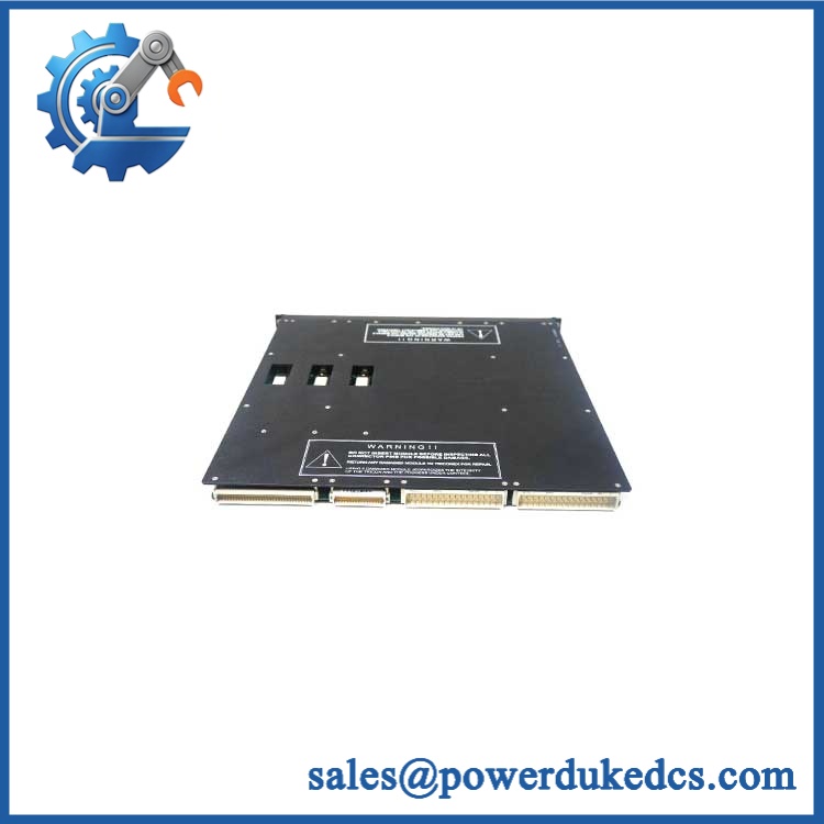
TRICONEX 3625C1
Module 5: Migration, Compatibility & Installation Traps
Replacement Matrix
Replacement Classification: Drop-in Replacement Within the Matching Tricon 3625 Configuration
A like-for-like 3625C1 replacement is appropriate where the existing Tricon v9–v11 system uses the 3625 architecture, compatible field termination, and the same environmental coating requirement. The C1 version belongs to Tricon’s urethane-conformal-coated model family and is explicitly identified as a 24 VDC 32-point TMR supervised/non-supervised commoned DO module.
3625C1 → 3625: Configuration and environmental compatibility review required. The underlying electrical function belongs to the same 3625 family, but C1 identifies the urethane-coated construction. In a corrosive or moisture-prone installation, a standard 3625 should not automatically be accepted as equivalent.
3625C1 → 3624: Hardware Modification Required. The 3624 is a 16-point supervised 24 VDC output module rated at 0.7 A per point, while 3625C1 provides 32 points and up to 1.7 A per point. Channel count, termination, and load capability are different.
3625C1 → 3604E: Hardware Modification Required. Both are 24 VDC TMR digital outputs, but 3604E is a 16-point non-supervised, non-commoned output module, whereas 3625C1 is a 32-point commoned supervised/non-supervised design.
⚠️ Field Traps — Watch Out
1. Do not confuse C1 with a cosmetic suffix: Tricon documentation defines C1 as urethane conformal coating. The coating is part of the environmental specification, particularly where moisture or chemical contamination is present.
2. Supervised versus non-supervised configuration: The 3625 supports both operating modes, but the field circuit requirements and diagnostic expectations differ. Confirm the application configuration before connecting a replacement; do not assume a supervised circuit can be rewired as a standard output without engineering approval.
3. Output-load margin: At the maximum 1.7 A point rating, the documented typical voltage drop is 2.8 VDC. Cable and termination losses add to that figure. Calculate the voltage available at the actual solenoid or relay coil rather than checking only the 24 VDC cabinet supply.
4. Commoned outputs: The 32 output points are commoned. The field return architecture must therefore be compatible with the 3625/3625C1 termination arrangement before power is applied.
Module 6: Quality Assurance SOP
Each TRICONEX 3625C1 should undergo a documented identification, electrical, diagnostic, and TMR test sequence before shipment.
- OEM identification visual inspection: Verify TRICONEX / Invensys markings, 3625C1 designation, serial number, hardware revision, front-panel labeling, connectors, and conformal-coating evidence.
- C1 coating verification: Confirm that the supplied assembly corresponds to the urethane-coated C1 configuration and record any visible revision or assembly-number information. Tricon introduced specific C1 assembly numbers for 3625C1 and 3625AC1 in later firmware documentation.
- Mechanical inspection: Examine the enclosure, PCB, connector interfaces, ejector hardware, coating condition, mounting surfaces, and exposed components for damage, corrosion, contamination, or evidence of unauthorized repair.
- Architecture verification: Confirm that the customer application requires the 32-point 24 VDC commoned TMR output architecture and identify whether supervised or non-supervised operation is required.
- Power verification: Install the unit in an approved Tricon test chassis and apply controlled field voltage within the documented 16–32 VDC range without exceeding 36 VDC.
- Power-on self-test (POST): Confirm expected startup behavior, module identification, PASS/FAULT/ACTIVE status, and field alarm indications.
- 32-channel output test: Exercise all 32 outputs independently using a controlled 24 VDC test fixture and approved representative loads.
- Current-load verification: Test representative channels below the 1.7 A per-point maximum and verify stable switching. Where transient testing is authorized, verify behavior against the 7 A / 10 ms surge characteristic.
- Voltage-drop test: Measure output voltage at representative load currents and document the relationship between field supply, output current, termination, and load-side voltage.
- Supervision test: For supervised applications, verify the authorized voltage/current loopback diagnostics and confirm detection of field-power loss, missing load, and applicable short-circuit conditions.
- Non-supervised test: Where the application uses non-supervised operation, verify normal switching without applying supervised-load assumptions to the field circuit.
- Diagnostic verification: Confirm PASS, FAULT, LOAD, and ACTIVE behavior and verify the expected channel-level fault reporting.
- TMR verification: Confirm that all three processor paths participate correctly and that the output voter produces the expected field command.
- Hot-spare verification: Where required, place the module in an approved standby arrangement and verify controlled replacement and module recognition behavior.
- Load simulation: Test representative solenoid or relay loads while monitoring current, output voltage, voltage drop, and fault indications.
- Extended stability test: Cycle representative outputs continuously while monitoring module temperature, field voltage, diagnostic state, and TMR communications.
- Final QC record: Retain complete part-number photographs, C1 coating verification, hardware revision, baseplate/termination reference, all-channel results, load data, supervision results, TMR verification, hot-spare results, and final QC approval.
The TRICONEX 3625C1 is a 32-point TMR 24 VDC digital output module in the Tricon v9–v11 family, with 16–32 VDC operation, 1.7 A maximum per point, 7 A surge for 10 ms, commoned outputs, supervised/non-supervised operation, and below 13 W module power loading.
The C1 suffix is an important environmental identifier: Tricon documentation places 3625C1 in the urethane conformal-coated product family. For spare-parts control, match the electrical function, supervised configuration, termination arrangement, hardware revision, and C1 environmental construction before releasing a replacement to a production safety system.











 Start Chat


