

Description
- Brand: TRICONEX / Invensys
- Full Model Number: 3635
- System/Series Family: Tricon v9–v11
- One-Sentence Core Function: 32-point simplex relay-contact digital output module with normally closed contacts
- Top 3 Hardcore Specs: 32 relay-contact outputs; normally closed output configuration; simplex architecture
- Stock Status: Stock condition and exact hardware revision to be confirmed
Module 3: Technical Product Introduction
When a control application needs dry-contact switching rather than a semiconductor output, the TRICONEX 3635 occupies a very different role from the conventional Tricon TMR digital-output modules. Model 3635 is identified as a simplex discrete output module using relay contacts, with 32 normally closed points. The module is intended for applications where the external circuit needs a relay-contact interface rather than a direct 24 VDC, 48 VDC, or 120 VDC electronic output. Tricon product-family references distinguish 3635/E from the separate 3636 family, which provides normally open relay contacts.
The simplex architecture is the key engineering characteristic. Unlike standard Tricon TMR output families, a simplex relay-output module does not provide three separately processed output paths for each field point. The available product identification also does not establish a universal voltage/current rating for every installed 3635 configuration, so the actual contact rating must be taken from the applicable hardware documentation and the physical module marking. That matters when the output drives an external relay, permissive circuit, annunciator, or other load… the relay contact rating, suppression method, and fail-state requirement all need to be checked before energization.
Module 4: Application Scenarios & Field Realities
- For interposing relay and permissive circuits, the 3635 provides a relay-contact interface rather than a powered transistor output. The receiving circuit therefore supplies the field-side voltage, while the Tricon module controls the relay contact state.
- Where a normally closed signal is required for a de-energized-safe external circuit, the 3635’s NC contact arrangement can be useful. Confirm exactly how the receiving device interprets contact opening, because a wiring or logic assumption made from a generic “digital output” label can reverse the intended fail-state behavior.
- In legacy Tricon cabinets with large numbers of discrete dry-contact interfaces, 32 points provide high contact density in one module position. Before replacement, document whether each channel is used as a control contact, alarm contact, permissive, or interlock signal; contact loads can differ significantly across the same card.
- During troubleshooting of an apparently failed output, measure the external circuit as well as the relay contact. An open circuit in a downstream fuse, interposing relay coil, or field terminal can look identical to a failed output if the diagnostic procedure checks only the receiving device.
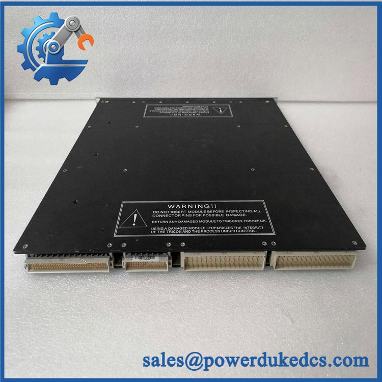
TRICONEX 3635
Module 5: Migration, Compatibility & Installation Traps
Replacement Matrix
Replacement Classification: Drop-in Replacement Only Within the Matching 3635 Relay-Contact Configuration
A like-for-like TRICONEX 3635 replacement is appropriate when the installed Tricon system uses the same 32-point simplex normally closed relay-output architecture and the replacement matches the applicable hardware revision, termination arrangement, and contact requirements. Product-family references explicitly identify 3635/E as a simplex discrete-output model with relay contacts, normally closed, 32 points.
3635 → 3636: Hardware Modification Required. The two families use different relay contact states: 3635 is identified as normally closed, while 3636 is identified as normally open. Substituting one for the other changes the field circuit’s normal state and can alter shutdown, alarm, or permissive behavior.
3635 → 3604E / 3607E: Hardware Modification Required. These are electronic TMR digital-output families with powered DC outputs, whereas 3635 is a simplex relay-contact interface. The field wiring, load behavior, diagnostic architecture, and fail-state characteristics are fundamentally different.
⚠️ Field Traps — Watch Out
1. Normally closed means contact topology, not guaranteed system fail-safe behavior: The 3635’s NC relay configuration must be interpreted together with the external circuit. A system can still be fail-unsafe if the receiving relay logic, field supply, or interposing wiring reverses the intended state.
2. Relay contact rating must be verified: Do not infer a universal current or voltage capacity from the model number. The allowable contact load depends on the applicable hardware specification and load type. Inductive loads can impose substantially higher transient stress than resistive loads.
3. Simplex versus TMR: Do not market or install the 3635 as a conventional TMR digital-output module. Product references explicitly classify it as simplex.
4. 3635 versus 3636 contact state: A replacement that changes NC to NO can produce a continuous process alarm, inhibit a permissive, or reverse the intended shutdown logic. Compare the actual field schematic before replacement.
Module 6: Quality Assurance SOP
Each TRICONEX 3635 should undergo a relay-contact-specific inspection and functional test before shipment.
- OEM identification visual inspection: Verify TRICONEX / Invensys markings, 3635 designation, serial number, hardware revision, connector arrangement, front-panel identification, and module condition.
- Architecture verification: Confirm the module is the simplex 32-point relay-contact, normally closed version required by the customer’s installation.
- Mechanical inspection: Examine the enclosure, PCB, relay components, connectors, ejectors, mounting surfaces, and visible relay/contact areas for corrosion, contamination, impact, or evidence of repair.
- Contact-state verification: Check every output point at rest and verify the expected normally closed state using calibrated continuity equipment.
- Energized-state test: Activate each channel through the approved test setup and confirm the relay contact transitions to the commanded state.
- Contact-resistance test: Measure representative closed-contact resistance and record the values against the applicable manufacturer specification.
- Open-circuit verification: Confirm the expected open-contact condition after relay actuation and verify that no unintended leakage or intermittent continuity is present.
- Contact-bounce observation: Monitor representative relay transitions with an oscilloscope or suitable contact-analysis instrument where required, particularly for timing-sensitive applications.
- Load simulation: Exercise representative resistive loads and, where authorized, representative inductive relay loads within the certified contact limits.
- Inductive-load protection check: Verify that the customer’s external suppression arrangement is present and correctly wired. Do not expose the test module to uncontrolled coil transients.
- Channel independence test: Operate individual relay points while monitoring adjacent channels to confirm there is no unintended mechanical or electrical interaction.
- System interface verification: Connect representative outputs to an approved test circuit and confirm correct contact-state recognition by the receiving relay or digital input.
- Extended cycling test: Cycle representative relay contacts repeatedly while monitoring contact stability, chatter, resistance, and module temperature.
- Final QC record: Retain complete part-number photographs, hardware revision, contact-state results, resistance measurements, load-test conditions, cycling results, and final QC approval.
The TRICONEX 3635 is a 32-point simplex relay-contact digital output module with normally closed contacts. Product-family documentation distinguishes it from semiconductor-based TMR digital-output modules and identifies the related 3636 family as the normally open relay-contact version.
For spare-parts control, the decisive attributes are simplex architecture, 32-point relay-contact construction, normally closed topology, approved contact-load capability, external suppression, and exact system wiring. Do not substitute the 3635 with an electronic TMR output or a normally open relay-output module without an engineering review.











 Start Chat


