

Description
- Brand: Triconex / Invensys
- Full Model Number: 3636R
- System/Series Family: Tricon v9–v11
- Core Function: 32-point non-triplicated relay output switching for non-critical field loads
- Top 3 Hardcore Specs: 32 non-commoned outputs; 125 VAC/VDC maximum; 2 A maximum per point
- Relay Contact: Normally Open (NO)
- Minimum Permissible Load: 10 mA at 5 VDC
- Resistive Switching Power: 2,000 VA / 150 W maximum
- Maximum Output Cycle Rate: <30 cycles/s
- Expected Relay Life: >10,000 cycles at maximum rated load
- Output Fuse: 2.5 A fast-acting per point
- Point Isolation: 1,500 VDC minimum
- Logic Power: <10 W all outputs Off; <20 W all outputs On
- Diagnostics: Relay loopback diagnostics; module PASS / FAULT / ACTIVE monitoring
- Hot Spare: Supported
- Termination: Separate external termination panel with cable interface to Tricon backplane
- Stock Status: New Surplus or Fully Tested Refurbished; exact revision to be confirmed
Tricon documentation identifies Model 3636R as a non-triplicated Relay Output module with 32 non-commoned normally-open relay outputs. It is intended for non-critical points that are not suitable for high-side solid-state output switching.
Module 3: Technical Product Introduction
When a field device requires a dry-contact style interface rather than a high-side semiconductor output, the TRICONEX 3636R provides the relay stage. It contains 32 individually referenced, normally-open relay outputs and is classified by Triconex as a non-triplicated relay-output module for non-critical points. The three processor channels provide output commands to the module, where the information is voted before driving the individual relay circuits. A loopback circuit independently verifies relay-switch operation, allowing the system to detect certain latent output faults even without relying on the external load.
Electrical limits are straightforward but should not be interpreted as a universal load rating. Each point is rated up to 2 A, with a maximum field voltage of 125 VAC/VDC and a minimum permissible load of 10 mA at 5 VDC. Resistive switching capacity is specified at 2,000 VA and 150 W maximum, while reactive-load switching requires derating to 25% of the maximum, or 37.5 W for DC applications. Each output is protected by a 2.5 A fast-acting fuse, and the 3636R provides minimum point isolation of 1,500 VDC.
Module 4: Application Scenarios & Field Realities
- For annunciator-panel interfaces, 3636R is a natural fit where the field circuit requires relay contacts rather than a direct solid-state output. Triconex specifically cites annunciator interfaces as an example of a non-critical application for the relay-output family.
- When switching auxiliary contactor, lamp, or indication circuits, the 32 non-commoned points allow separate field references at each output. This is useful in cabinets with mixed-voltage auxiliary circuits, provided every individual load remains within its voltage, current, switching-power, and fuse limits.
- For legacy Tricon cabinets undergoing maintenance, the relay loopback feature provides an important diagnostic layer. The module can verify relay-switch operation independently of the connected field load, so a field-circuit fault does not automatically have to be interpreted as a failed relay card.
- Where outputs drive inductive loads, the nominal 2 A figure can be misleading. Tricon documentation requires substantial switching-power derating for reactive loads, and incandescent lamps may produce inrush currents 10–15 times their nominal current. Actual load characteristics therefore need to be included in the engineering calculation.
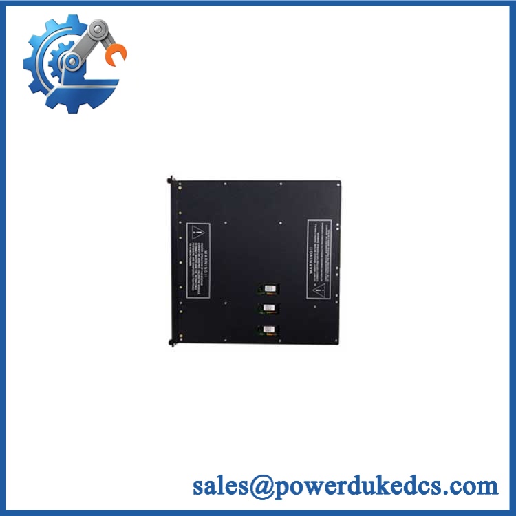
TRICONEX 3636R
Module 5: Migration, Compatibility & Installation Traps
Replacement Matrix
Replacement classification: Drop-in Replacement when the existing Tricon installation is configured for Model 3636R with the compatible external termination panel, field-voltage arrangement, and supported system configuration.
Software compatibility: Configuration verification required. No application firmware is stored on the relay contacts themselves, but output assignments, diagnostic handling, active/spare configuration, and the Tricon application remain part of the replacement procedure.
Cross-model replacement: Hardware and application verification required. The related 3636T has a different point-isolation rating, while other Tricon output families may use solid-state switches, different field voltages, commoning schemes, or different diagnostic architectures.
Field Traps — Watch Out
1. Do not confuse 3636R with a TMR relay output card. The module is classified as non-triplicated relay output. Although three processor channels provide voted commands to the module, the relay-output function itself is not a triplicated field-output architecture. It is intended for non-critical points.
2. Verify the actual load type before using the 2 A specification. A 2 A resistive load is not equivalent to a 2 A inductive load. Tricon’s guidance reduces allowable switching power to 25% of maximum for reactive loads, and high-inrush incandescent loads require their peak current to be included in the calculation.
3. Inspect the external fuse before condemning the module. Each output has a 2.5 A fast-acting fuse. An open fuse can interrupt a perfectly healthy relay contact, producing a field-side failure that originates outside the relay itself.
4. Match the termination panel and cable assembly. The 3636R requires a separate external termination panel connected to the Tricon backplane. The replacement process therefore includes the ETP, cable interface, field wiring, and fuse arrangement—not merely the front-panel module.
5. Verify relay-cycle duty. The specified maximum output cycle rate is below 30 cycles per second, and expected life is greater than 10,000 cycles at maximum rated load. A fast-cycling control loop can therefore have a very different maintenance profile from a simple status relay.
Module 6: Quality Assurance SOP
Pre-Shipment Inspection Protocol for TRICONEX 3636R
- OEM identity inspection: Verify Triconex/Invensys marking, exact 3636R designation, hardware revision, serial number, front-panel label, and additional assembly identifiers.
- Variant verification: Confirm the module is 3636R, not 3636T or another Tricon relay/output model.
- Mechanical inspection: Examine the enclosure, module guides, locking mechanism, relay-output connector, status LEDs, accessible PCB surfaces, and mounting interfaces for corrosion, contamination, deformation, cracked components, or unauthorized repair.
- Relay-contact inspection: Check accessible relay/output interfaces for contamination, oxidation, mechanical damage, or evidence of overheating.
- Termination inspection: Verify the external termination panel and cable interface intended for the installation; inspect terminals, fuse holders, and field connections before energization.
- Fuse verification: Confirm one 2.5 A fast-acting fuse per output and inspect for correct seating, continuity, discoloration, and thermal damage.
- Power-on self-test: Install the module in a compatible Tricon test chassis and verify PASS, FAULT, ACTIVE, and individual point indications.
- 32-channel verification: Exercise all 32 output points independently and record each result.
- Relay switching test: Operate every relay under a controlled low-voltage test load and verify clean normally-open contact closure and release.
- Contact resistance test: Measure relay contact resistance under an approved low-current test condition and record abnormal or unstable values.
- Load test: Apply representative resistive loads within the documented 2 A / 150 W limits and verify switching performance, voltage drop, and thermal behavior.
- Reactive-load verification: Where appropriate, test an approved representative inductive load using the documented derated switching-power limits rather than the full resistive rating.
- Minimum-load test: Verify representative operation at loads above the documented 10 mA, 5 VDC minimum permissible load.
- Loopback diagnostic verification: Exercise the relay loopback circuit and confirm that controlled relay faults are detected without relying on the external load.
- Fuse-fault simulation: Where the laboratory fixture permits, simulate an appropriately controlled fuse-open condition and verify the expected diagnostic response.
- TMR command-path verification: Where the test environment permits, validate all three processor command channels and confirm correct voted relay operation.
- Hot-spare test: Use a compatible active/spare Tricon arrangement and verify transfer behavior according to the approved maintenance procedure.
- Cycle-duty test: Operate representative relay channels at an appropriate controlled cycle rate and inspect for contact bounce, welding, sticking, excessive heating, or diagnostic instability.
- Isolation verification: Perform an approved controlled isolation test against the 1,500 VDC minimum point-isolation specification for the 3636R.
- Thermal observation: Run representative multiple-channel loads for an extended interval and monitor relay areas, fuse holders, connectors, and the module body for abnormal temperature rise.
- Final QC record: Record exact model, revision, serial number, termination-panel identity, fuse configuration, all 32 relay results, contact measurements, load-test results, loopback diagnostics, isolation result, hot-spare test where applicable, test duration, and inspector approval.
- ESD-controlled packaging: Place the module in an ESD-safe package and protect connectors, relay interfaces, locking features, and PCB surfaces against impact, moisture, contamination, and electrostatic discharge.
Procurement note: The technically supported identity is TRICONEX 3636R — 32-point Non-Triplicated Relay Output Module. Published Tricon documentation specifies normally-open contacts, 32 non-commoned points, 125 VAC/VDC maximum field voltage, 2 A maximum current per point, 10 mA at 5 VDC minimum permissible load, 2,000 VA / 150 W maximum resistive switching power, <30 cycles/s maximum output rate, 2.5 A fast-acting fuses, and 1,500 VDC minimum point isolation. The module is intended for non-critical points, uses an external termination panel, and supports hot-spare operation.











 Start Chat


