

Description
- Brand Triconex / Invensys
- Full Model Number 3720 / Model 3720
- System/Series Family Tricon v10.2 and later Safety Instrumented System
- Core Function TMR acquisition of 64 single-ended analog voltage inputs
- Top 3 Hardcore Specs 64 inputs | 0–5 VDC nominal | 12-bit or 14-bit programmable resolution
- Stock Status New Surplus — verify hardware revision, chassis generation, termination arrangement, and input configuration before shipment
Module 3: Technical Product Introduction
A voltage-input failure can corrupt an entire group of process measurements while leaving the controller and field transmitter power apparently normal. Triconex 3720 is a 64-point TMR analog input module designed for 0–5 VDC single-ended signals. The module processes the same field measurement through three independent channels, allowing the Tricon architecture to compare the redundant readings and identify channel discrepancies. Tricon technical documentation specifies that Model 3720 can be installed only in Tricon v10.2 and later systems, although upgraded low-density chassis may also support it under the documented compatibility rules.
The conversion architecture provides 12-bit or 14-bit programmable resolution, a 10 ms input update rate, and accuracy better than 0.15% of full scale from 0°C to 60°C. Each input presents at least 10 MΩ DC input resistance, while typical channel-to-channel isolation is approximately 420 kΩ. The module also accepts 0–20 mA signals through a 250 Ω shunt, measures approximately 0–5.3 VDC with its +6% over-range, and provides at least 800 VDC field-to-system isolation.
Module 4: Application Scenarios & Field Realities
- For process instrumentation using voltage transmitters, the 3720 provides 64 single-ended measurement points in one TMR input assembly. Before card replacement, inject a calibrated voltage at the field termination; this is usually faster than swapping transmitters one at a time.
- Where measurement accuracy matters near an alarm or trip threshold, the programmable 12/14-bit resolution and stated <0.15% full-scale accuracy provide the measurement baseline, but the complete loop still depends on transmitter accuracy, wiring, grounding, scaling, and configured engineering limits.
- For legacy low-density Tricon installations upgraded to v10.2.x or later, the 3720 can be used where the documented low-density compatibility conditions are satisfied. The chassis generation should be checked before shipment rather than assuming any older Tricon carrier will accept the module.
- When a 0–20 mA signal must be acquired, the module can use a 250 Ω shunt resistor to convert current into a voltage input. That resistor becomes part of the measurement path; its tolerance and condition should therefore be included in calibration checks.
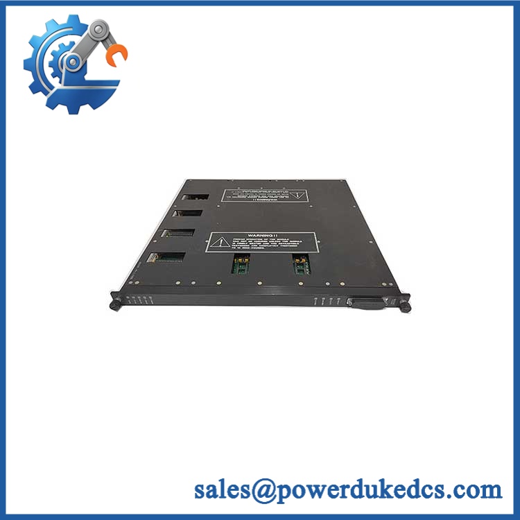
Triconex 3720
Module 5: Migration, Compatibility & Installation Traps
Replacement Matrix
| Replacement Status | Engineering Assessment |
|---|---|
| Drop-in Replacement | Yes, for a like-for-like 3720 installation in a compatible Tricon v10.2+ chassis with the approved baseplate, termination hardware, and input configuration. |
| Software Compatible | Generally yes for an exact module replacement, but channel assignments, configured voltage/current mode, scaling, diagnostics, and TriStation database settings must be verified. |
| Hardware Modification Required | Normally no for an exact 3720 replacement. Hardware changes may be required when changing chassis generation, termination architecture, or moving to another analog-input family. |
⚠️ Field Traps: Watch Out
Do not confuse 3720 with 3721. Both are yellow TMR analog-input modules, but 3720 provides 64 single-ended 0–5 VDC inputs, while 3721 provides 32 differential DC-coupled inputs and a different voltage configuration.
Verify the chassis generation. The technical specification states that the 3720 can be installed only in Tricon v10.2 and later systems, with a documented exception for certain upgraded low-density systems. An older chassis should not be treated as automatically compatible.
Check the actual signal type. The primary input range is 0–5 VDC. If the existing field device produces current, confirm the approved 250 Ω shunt arrangement before connecting it. Do not assume that every 4–20 mA transmitter can be connected directly.
Watch rapidly changing signals during diagnostics. The documented channel-comparison logic can defer comparison when an input sample changes by more than 0.25% from the previous sample. Rapid process transients can therefore affect the timing of fault detection.
Do not use input resistance as a substitute for loop design. The minimum DC input resistance is 10 MΩ, but the complete field circuit still depends on the transmitter output impedance, cable characteristics, shunt resistor when applicable, and grounding arrangement.
Module 6: Quality Assurance SOP
A surplus 3720 should be tested as a 64-channel TMR analog acquisition module. A module-level power-up test alone does not establish measurement accuracy.
- OEM anti-counterfeit visual inspection: Verify Triconex/Invensys identification, exact 3720 designation, yellow identification color, PCB revision, connector geometry, front-panel labels, and manufacturing identifiers against controlled references.
- Part-number and traceability check: Record model number, hardware revision, serial number, date code, and associated baseplate and termination references.
- Mechanical inspection: Examine the backplane connector, enclosure, ejector/keying hardware, PCB, and field interface for bent contacts, corrosion, contamination, cracking, or unauthorized rework.
- Power-on self-test (POST): Install the module in an approved Tricon test arrangement and verify expected PASS, FAULT, ACTIVE, and FIELD status behavior.
- Supply verification: Apply the approved system supply using a controlled fixture and monitor module power consumption. Published documentation specifies less than 12 W logic power.
- 64-channel voltage test: Exercise all 64 input points using calibrated voltage sources across representative points in the 0–5 VDC range.
- Resolution verification: Where the test fixture supports it, verify operation in both the documented 12-bit and 14-bit programmable resolution modes.
- Accuracy verification: Test representative low-, mid-, and full-scale input values and compare the measured values against the applicable <0.15% full-scale accuracy requirement over the specified temperature range.
- Over-range verification: Apply controlled signals up to the documented 0–5.3 VDC measurement over-range and confirm correct module behavior without exceeding the approved test limits.
- Current-input verification: Where the installation uses current inputs through the 250 Ω shunt, inject calibrated 0–20 mA signals and verify correct converted measurement values.
- Input-resistance test: Verify representative channels against the documented minimum 10 MΩ DC input resistance.
- Power-off resistance check: Measure representative inputs against the documented typical 140 kΩ power-off resistance where the approved test fixture permits.
- Channel-isolation verification: Verify representative channel-to-channel electrical behavior and isolation against the documented approximately 420 kΩ typical channel-to-channel characteristic.
- Field-to-system isolation test: Use the approved laboratory procedure to verify the specified 800 VDC minimum field-to-system isolation.
- TMR comparison test: Inject the same calibrated signal into the three redundant processing paths and confirm consistent measurement, disagreement detection, and diagnostic response under controlled single-channel deviation.
- Diagnostic timing test: Apply controlled changing inputs and verify the configured fault-detection behavior while accounting for the documented comparison rules for rapidly changing measurements.
- System recognition test: Verify correct module recognition, point addressing, status reporting, and data exchange through the Tricon I/O architecture.
- Communication handshake verification: Confirm successful transfer of all 64 analog values from the module to the Tricon processors. The 3720 itself is an analog I/O module rather than a standalone Ethernet or Modbus interface.
- Scaling and configuration verification: Compare every tested channel against the approved TriStation configuration, engineering range, tag assignment, and selected 0–5 VDC or current-input mode.
- Extended-run test: Operate representative channels continuously while monitoring measurement stability, diagnostic events, supply current, and abnormal temperature rise.
- Final QC record: Document hardware revision, supply measurements, all 64 channel results, resolution mode, accuracy checks, over-range behavior, current-input/shunt configuration where applicable, isolation tests, TMR diagnostics, system recognition, extended-run observations, traceability, and packaging condition.
Technical Identification Note: Tricon documentation identifies Model 3720 as a TMR analog input module with 64 single-ended inputs for 0–5 VDC signals, installable in Tricon v10.2 and later systems. The controlled specification lists a 10 ms input update rate, 12-bit or 14-bit programmable resolution, <0.15% full-scale accuracy from 0°C to 60°C, ≥10 MΩ input resistance, 0–5.3 V over-range measurement, optional 0–20 mA input through a 250 Ω shunt, and 800 VDC minimum field-to-system isolation.











 Start Chat


