

Description
- Brand: TRICONEX
- Full Model Number: 3721
- System/Series Family: Tricon v10.2 and later TMR safety system
- Core Function: 32-channel TMR analog input acquisition for 0–5 VDC or -5 to +5 VDC differential signals
- Top 3 Hardcore Specs: 32 differential inputs; 0–5 VDC / -5 to +5 VDC; 12/14-bit programmable resolution
- Stock Status: Verify current New Surplus, Factory Sealed, or Fully Tested Refurbished condition before order
Module 3: Technical Product Introduction
A high-density analog card becomes difficult to replace when the field signal, chassis generation, and termination hardware are all interdependent. The TRICONEX 3721 is a 32-point TMR analog input module specified for Tricon v10.2 and later systems. Triconex documentation defines the module for 0–5 VDC or -5 to +5 VDC differential, DC-coupled inputs, with three independent input channels processing each field signal before the TMR system distributes the values to the Main Processors. The module is therefore intended for voltage-based process instrumentation rather than direct 4–20 mA measurement.
The measurement architecture provides 12-bit or 14-bit programmable resolution, with an input update rate of approximately 10 ms in published technical specifications. Accuracy is specified at less than 0.15% of full-scale range from 0°C to 60°C, with common-mode rejection better than -85 dB from DC to 100 Hz. Continuous input protection is specified to 150 VDC / 115 VAC. Triconex documentation also permits current-loop measurement by using an appropriate external shunt arrangement; the exact resistor value must match the selected voltage range and termination design.
Module 4: Application Scenarios & Field Realities
- For process transmitters providing voltage outputs, the 3721 is suited to 0–5 VDC and bipolar -5 to +5 VDC instrumentation. Pressure, level, position, and other conditioned process variables can be acquired as differential voltage signals across its 32 channels.
- Inside a heavily populated Tricon v10.2 or later cabinet, the three-channel TMR architecture allows each analog signal to be processed independently for system voting and diagnostics. This is particularly relevant where an input measurement participates directly in shutdown permissives or protective logic.
- When interfacing 4–20 mA instruments, do not assume that 3721 is a native current-input card. Triconex documentation identifies the module as a voltage-input device; 4–20 mA measurement can be achieved through an external shunt resistor arrangement. The resistor value, power dissipation, transmitter burden, and configured voltage range all need to be checked as one circuit.
- During legacy Tricon replacement, confirm the controller generation before purchasing. The 3721 is documented specifically for Tricon v10.2 and later, so an older Tricon installation should not be upgraded to this module solely because its connector or channel count appears similar.
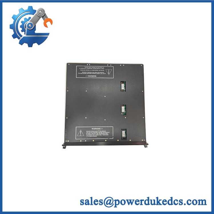
TRICONEX 3721
Module 5: Migration, Compatibility & Installation Traps
Replacement Matrix
Exact 3721 with matching Tricon v10.2+ configuration: Drop-in Replacement
When the installed controller, baseplate, termination arrangement, field signal range, and project configuration all correspond to Model 3721, the module can normally be exchanged as a like-for-like hardware replacement.
3721 revision change: Software Compatible / Configuration Verification Required
Record the existing module revision, configured input range, scaling, diagnostics, and termination arrangement before replacement. Verify the same parameters after installation.
3700A or 3703E substituted for 3721: Hardware Modification Required
These modules have different channel configurations and electrical architectures. 3703E provides 16 isolated inputs, while 3721 provides 32 differential DC-coupled inputs; physical compatibility should not be inferred from the common Tricon module family.
RH916GG substituted as part of a 3721 replacement: Hardware Modification Required / Identifier Mismatch
The supplied string RH916GG does not identify a Triconex 3721 accessory in the technical material reviewed. Schneider Electric’s current Foxboro documentation identifies RH916GG as a 20 m Type 4H P/PVC cable associated with Foxboro FBM242 termination assemblies, not as a Triconex 3721 component.
⚠️ Field Traps (Watch Out)
Model-and-accessory mismatch: The requested designation combines TRICONEX 3721 with RH916GG. These identifiers belong to different product families in the available technical evidence. The 3721 is a Tricon analog input module, while RH916GG is documented as a Foxboro termination cable. Keep the two identifiers separate in the purchasing record unless the original cabinet BOM explicitly shows an engineered interface between them.
Signal-range trap: The native 3721 input ranges are 0–5 VDC and -5 to +5 VDC. A 4–20 mA transmitter requires an external shunt arrangement. Do not configure the application as a direct current input without confirming the termination circuit and resistor arrangement.
Generation trap: Model 3721 is specified for Tricon v10.2 and later. Before replacing an older 3700-series module, establish the exact controller version and approved module list.
Common-mode trap: Differential inputs do not mean unlimited field-potential separation. Verify the documented common-mode range and field-to-ground potential before wiring a replacement card into a cabinet with separate instrument power domains.
Module 6: Quality Assurance SOP
Pre-Shipment QA Protocol for TRICONEX 3721
- Step 1 — Identity Verification: Confirm TRICONEX marking, Model 3721 designation, serial number, hardware revision, manufacturing data, and associated Tricon baseplate/termination information.
- Step 2 — OEM Anti-Counterfeit Visual Inspection: Inspect labels, barcodes, PCB markings where accessible, connector geometry, mechanical keying, fasteners, status indicators, and evidence of unauthorized component replacement.
- Step 3 — Mechanical Inspection: Check the enclosure, card-edge connector, field interface, alignment features, retaining mechanism, and housing for cracks, corrosion, contamination, or deformation.
- Step 4 — Analog Test Fixture Verification: Prepare calibrated 0–5 VDC and -5 to +5 VDC differential sources and verify that the fixture remains within the documented input protection and common-mode limits.
- Step 5 — Power-On Self-Test: Install the module in an approved Tricon v10.2+ test chassis and verify normal startup, module recognition, PASS/FAULT/ACTIVE indications, and absence of diagnostic errors.
- Step 6 — Thirty-Two-Channel Test: Exercise all 32 differential input channels individually at low-scale, mid-scale, and full-scale reference points. Record measured values and diagnostic status.
- Step 7 — Resolution and Accuracy Verification: Confirm configured 12-bit or 14-bit measurement behavior using calibrated instrumentation and compare readings against the reference source.
- Step 8 — Diagnostic Verification: Check the TMR input-processing diagnostics under stable test conditions and verify that no unexplained channel mis-compare or module fault is generated.
- Step 9 — Current-Loop Interface Test: When the supplied unit is intended for a shunt-based 4–20 mA application, verify the approved resistor arrangement, measured voltage conversion, scaling, and transmitter-loop burden before release.
- Step 10 — Final QC Record: Record model, serial number, hardware revision, all 32 channel results, configured range, accuracy results, diagnostic status, visual condition, test date, and final QC disposition.
Technical Verification Note: Triconex documentation identifies 3721 as a TMR analog input module with 32 differential DC-coupled inputs and selectable 0–5 VDC or -5 to +5 VDC ranges, and states that it can be installed only in Tricon v10.2 and later systems. Available technical specifications list 12-bit or 14-bit programmable resolution, approximately 10 ms input update rate, less than 0.15% FSR accuracy from 0°C to 60°C, and continuous input overrange protection to 150 VDC / 115 VAC.
Part-Number Verification Note: The user-supplied RH916GG should not be represented as part of the Triconex 3721 module without further cabinet-level evidence. Schneider Electric’s current Foxboro documentation identifies as a 20 m Type 4H P/PVC cable for FBM242 termination assemblies, which indicates a separate Foxboro product family.











 Start Chat


