
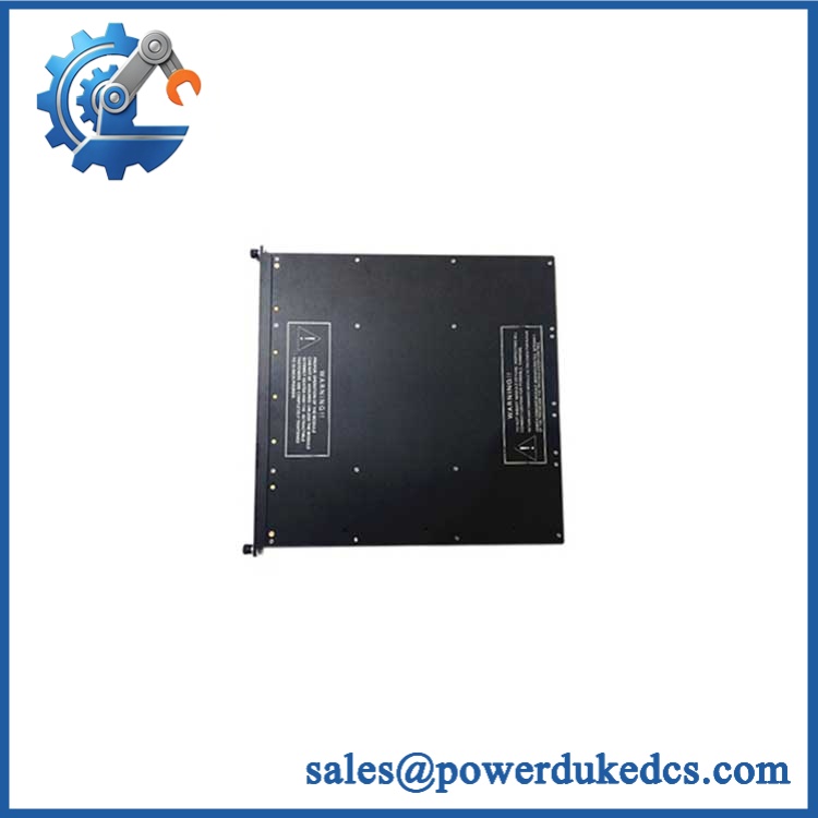

Description
- Brand: TRICONEX
- Full Model Number: 3721-C1 / 3721C1
- System/Series Family: Tricon v10.2 and later TMR safety system
- Core Function: 32-channel differential TMR analog input acquisition for 0–5 VDC or -5 to +5 VDC process signals
- Top 3 Hardcore Specs: 32 differential DC-coupled inputs; 12/14-bit programmable resolution; 10 ms input update rate
- Stock Status: Verify current New Surplus, Factory Sealed, or Fully Tested Refurbished condition before order
Module 3: Technical Product Introduction
A replacement analog-input card must match more than channel count. The TRICONEX 3721-C1, also written 3721C1, is the C1 version of the Tricon Model 3721 TMR analog-input module, providing 32 differential, DC-coupled inputs for 0–5 VDC or -5 to +5 VDC signals. Triconex documentation places the 3721 family in Tricon v10.2 and later systems and describes three independent input channels per point, with each channel converting the field signal to digital data for the three Main Processors. A mid-value selection algorithm is used within the TMR architecture.
The C1 designation is important for lifecycle identification. Triconex documentation lists 3721C1 among the urethane-conformal-coated models, while the underlying 3721 electrical architecture remains a 32-point differential TMR analog input. Published specifications include 12-bit or 14-bit programmable resolution, a 10 ms input update rate, accuracy below 0.15% of full-scale range from 0°C to 60°C, 10 MΩ minimum DC input resistance, and 150 VDC continuous / 115 VAC continuous input over-range protection. The 3721 also supports 0–20 mA measurement through an external 250 Ω shunt resistor.
Module 4: Application Scenarios & Field Realities
- For process transmitters producing voltage signals, 3721-C1 is suited to 0–5 VDC and bipolar -5 to +5 VDC instrumentation. The input range is software-selectable through TriStation 1131, so the configured range must match the transmitter and application scaling.
- Inside a high-density Tricon safety cabinet, the 32-channel differential architecture allows many process measurements to be acquired through one module while retaining TMR processing. This is useful for pressure, level, position, and other conditioned process signals that participate in shutdown or permissive logic.
- When field circuits operate at different electrical potentials, the 3721 architecture includes field-to-system isolation, with published documentation specifying 800 VDC minimum isolation. That should not be interpreted as unlimited common-mode tolerance; the same specification limits common-mode voltage to approximately -12 V to +12 V peak.
- During a retrofit involving HART instrumentation, 3721 can be used with the Triconex 2770H HART Analog Input Interface Module, which documentation identifies as compatible with Model 3721 and capable of handling the associated HART field-device interface.
Module 5: Migration, Compatibility & Installation Traps
Replacement Matrix
Exact 3721-C1 / 3721C1 with matching Tricon configuration: Drop-in Replacement
When the installed system uses the same 3721 family, approved chassis and termination hardware, compatible firmware, and matching project configuration, the replacement can generally be handled as a like-for-like module exchange.
3721 to 3721-C1: Software Compatible / Hardware-Revision Verification Required
The electrical function remains the Model 3721 analog-input architecture, while the C1 designation identifies a conformal-coated version. Verify the installed hardware revision, assembly number, project compatibility, and environmental requirements before substitution. Tricon documentation specifically lists 3721C1 under the urethane-conformal-coated models.
3703EC1 substituted for 3721-C1: Hardware Modification Required
3703E/3703EC1 is a 16-channel isolated analog-input family for 0–5 VDC or 0–10 VDC. The 3721-C1 provides 32 differential DC-coupled channels and supports bipolar -5 to +5 VDC, so the channel architecture and signal range are different.
⚠️ Field Traps (Watch Out)
C1 lifecycle trap: The C1 suffix is not a different signal function from the basic 3721 specification; it identifies a conformal-coated configuration within the Tricon product family. Do not create a new application specification merely because the physical label ends in C1, but do preserve the exact C1 identification in the spare-parts record.
Input-range trap: The module supports 0–5 VDC or -5 to +5 VDC, with the selected range configured through TriStation 1131. A replacement can pass a basic hardware test and still produce incorrect engineering values if the project range or scaling is wrong.
Shunt-resistor trap: A 4–20 mA instrument is not a native current-input connection on the 3721. Triconex documentation specifies 0–20 mA using a 250 Ω shunt, so the resistor, loop burden, voltage range, and application scaling must be treated as one engineered circuit.
Common-mode trap: Differential inputs do not eliminate common-mode limits. The published 3721 specification gives a common-mode voltage range of approximately -12 V to +12 V peak. Measure field-to-field and field-to-ground potentials before commissioning a replacement.
Module 6: Quality Assurance SOP
Pre-Shipment QA Protocol for TRICONEX 3721-C1
- Step 1 — Identity Verification: Confirm TRICONEX marking, 3721-C1 / 3721C1 designation, serial number, hardware revision, assembly information, and any available conformal-coating identification.
- Step 2 — OEM Anti-Counterfeit Visual Inspection: Inspect labels, barcodes, PCB markings where accessible, coating appearance, connector geometry, mechanical keys, retaining hardware, and evidence of unauthorized component replacement.
- Step 3 — Mechanical Inspection: Check the enclosure, card-edge connector, field interface, keying features, retaining mechanism, and PCB surfaces for cracking, contamination, corrosion, coating damage, or deformation.
- Step 4 — Analog Test Fixture Verification: Prepare calibrated differential sources for both 0–5 VDC and -5 to +5 VDC testing. Confirm the fixture remains inside the specified common-mode and over-range limits.
- Step 5 — Power-On Self-Test: Install the module in an approved Tricon v10.2+ test chassis and verify normal startup, module recognition, PASS/FAULT/ACTIVE/appropriate FIELD indication, and absence of diagnostic faults.
- Step 6 — Thirty-Two-Channel Input Test: Exercise all 32 differential channels individually at low-scale, mid-scale, and full-scale reference values. Record measured values and diagnostic status.
- Step 7 — Resolution and Accuracy Verification: Test representative points using the configured 12-bit and/or 14-bit operating mode where the approved laboratory procedure permits, and compare results with calibrated instrumentation.
- Step 8 — Isolation and Diagnostic Verification: Verify the approved field-to-system isolation and run the module’s diagnostic routines under stable test conditions, checking for unexpected channel faults or TMR mis-compares.
- Step 9 — Current-Loop Interface Test: Where the spare is intended for shunt-based 4–20 mA applications, verify the correct 250 Ω shunt arrangement, resulting voltage signal, scaling, and loop burden before release.
- Step 10 — Final QC Record: Record model, serial number, hardware revision, assembly number, input ranges tested, all 32 channel results, diagnostic status, visual condition, test date, and final QC disposition.
Technical Verification Note: Triconex documentation identifies 3721C1 as the conformal-coated version of the Model 3721 TMR analog-input module. The 3721 architecture provides 32 differential DC-coupled inputs, configurable for 0–5 VDC or -5 to +5 VDC, with 12-bit or 14-bit programmable resolution, a 10 ms input update rate, and less than 0.15% FSR accuracy from 0°C to 60°C. The module supports 0–20 mA through a 250 Ω shunt resistor and is specified for Tricon systems beginning with v10.2.
Part-Number Control Note: Public technical documentation treats 3721C1 as the exact C1-designated form of Model 3721, not as a separate analog-input function. An unrelated web listing that maps “3721-C1” to an 873EC analyzer conflicts with Triconex documentation and should not be used for Triconex spare identification.











 Start Chat


