

Description
- Brand: Triconex / Invensys
- Full Model Number: 3721A
- System/Series Family: Tricon v10.2 and later
- Core Function: 32-channel differential TMR analog input acquisition for 0–5 VDC or -5 to +5 VDC signals
- Top 3 Hardcore Specs: 32 differential DC-coupled inputs; 0–5 VDC or -5 to +5 VDC; 12-bit or 14-bit programmable resolution
- Input Update Rate: 10 ms
- Accuracy: <0.15% of full-scale range from 0°C to 60°C
- Input Resistance: 10 MΩ DC minimum
- Common-Mode Range: -12 VDC to +12 VDC peak
- Common-Mode Rejection: -85 dB, DC to 100 Hz typical
- Channel-to-Channel Isolation: 420 kΩ typical
- Input Overrange: +6%; approximately -5.3 to +5.3 VDC
- Input Protection: 150 VDC continuous / 115 VAC continuous
- Current Input: 0–20 mA using a 250 Ω shunt resistor
- Field-to-System Isolation: 800 VDC minimum
- Diagnostics: TMR input diagnostic fault detection
- Status Indicators: PASS, FAULT, ACTIVE, FIELD
- Logic Power: <12 W
- Stock Status: New Surplus or Fully Tested Refurbished; exact hardware revision to be confirmed
Tricon documentation identifies the 3721 as a TMR differential analog-input module with 32 differential DC-coupled inputs, selectable 0–5 VDC or -5 to +5 VDC input ranges, and installation limited to Tricon v10.2 and later. Newer Tricon documentation uses the “3721a” notation in its module table for this version.
Module 3: Technical Product Introduction
A voltage-input module becomes a critical measurement point when the transmitter or packaged instrument is referenced to a different electrical potential from the control-system common. The TRICONEX 3721A is a 32-channel differential TMR analog input module intended for Tricon systems v10.2 and later. Each input is DC-coupled, and the module can be configured for either 0–5 VDC or -5 to +5 VDC measurement. Like other Tricon analog-input modules, it uses three independent input channels and a mid-value selection method to maintain a valid process value when the three measurements are compared.
The acquisition specification is unusually useful for field qualification. The module updates inputs every 10 ms, provides 12-bit or 14-bit programmable resolution, and specifies accuracy below 0.15% of full-scale range from 0°C to 60°C. Input resistance is at least 10 MΩ, while the common-mode range is -12 to +12 V peak with typical common-mode rejection of -85 dB from DC to 100 Hz. A 0–20 mA signal can also be measured through a 250 Ω shunt resistor.
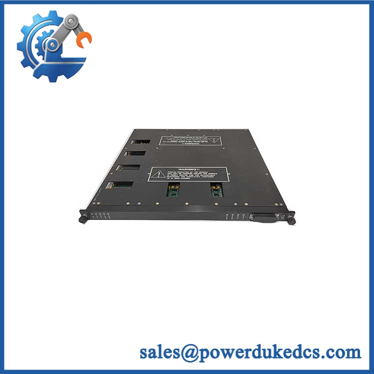
TRICONEX 3721A
Module 4: Application Scenarios & Field Realities
- For packaged analyzers and instrumentation delivering voltage outputs, 3721A provides a differential measurement path instead of forcing the field signal into a single-ended architecture. That distinction matters when the instrument’s signal reference is not at the same potential as the control cabinet common.
- Where an existing 4–20 mA instrument must be interfaced through a voltage-input architecture, the documented 0–20 mA capability with a 250 Ω shunt provides an electrical path for current-to-voltage conversion. The signal scaling in the Tricon application must still reflect the selected input configuration.
- For low-level process measurements routed through electrically noisy cabinets, the differential input and approximately -85 dB common-mode rejection can be important when common-mode interference exists on the field wiring. That does not eliminate the need for correct shielding, grounding, pair routing, and termination practices.
- During a Tricon v10.2 or later upgrade, 3721 can be particularly useful when the existing low-density chassis has been migrated to a later software/hardware generation. Tricon documentation specifically notes that Model 3721 can be installed in certain low-density systems upgraded to v10.2.x or later, subject to the documented chassis-compatibility appendix.
Module 5: Migration, Compatibility & Installation Traps
Replacement Matrix
Replacement classification: Drop-in Replacement when the existing Tricon installation is documented for the same 3721/3721A hardware generation, compatible chassis, termination arrangement, field wiring, and system revision.
Software compatibility: Configuration verification required. The input range is configurable through the Tricon engineering environment, so the application must retain the correct 0–5 VDC or -5 to +5 VDC scaling, channel assignments, alarms, and diagnostic configuration.
Cross-model replacement: Hardware and configuration verification required. The 3721 is materially different from 3720, 3703E, and 3704E. The 3720 is a 64-point single-ended module, while 3721 provides 32 differential inputs. The 3703E and 3704E use different voltage-input architectures and channel densities.
Field Traps — Watch Out
1. Confirm the exact module naming on the hardware. Tricon documentation commonly calls the component Model 3721, while newer module tables use the 3721a notation in a footnote. Do not interpret the “A” as proof of a completely different electrical model until the physical label, hardware revision, and project documentation have been checked.
2. Do not confuse differential and single-ended architecture. A 3721 input uses a differential measurement path. Rewiring a cabinet designed for the 3720’s single-ended topology can change the signal reference and introduce common-mode errors or invalid measurements.
3. Respect the ±12 V common-mode range. A differential signal can be within its nominal ±5 V measurement span while both conductors sit at an excessive common-mode voltage. The published -12 to +12 V peak common-mode range therefore needs to be checked separately from the process signal itself.
4. Check the shunt configuration carefully. When using the module for current-input measurement, the 250 Ω shunt resistor becomes part of the loop burden. A transmitter already operating near its compliance-voltage limit may not tolerate additional resistance without recalculation.
5. Confirm the chassis generation. The 3721 can be installed only in Tricon v10.2 and later systems, with specific provisions for certain upgraded low-density systems. It should not be treated as a universal replacement for older Tricon analog-input modules.
Module 6: Quality Assurance SOP
Pre-Shipment Inspection Protocol for TRICONEX 3721A
- OEM identity inspection: Verify Triconex/Invensys marking, Model 3721/3721A designation, hardware revision, serial number, front-panel markings, and all additional assembly identifiers.
- Revision verification: Record the exact hardware revision and compare it with the customer’s installed module, particularly where the purchasing record uses “3721A” while the manufacturer documentation uses Model 3721 terminology.
- Mechanical inspection: Examine the housing, module guides, locking hardware, backplane interface, front-panel LEDs, connector surfaces, and accessible PCB areas for corrosion, contamination, deformation, cracked components, or unauthorized repair.
- Connector inspection: Check the module and field termination interfaces for oxidation, bent contacts, damaged housings, loose hardware, or contamination.
- Power-on self-test: Install the module in a compatible Tricon v10.2-or-later test chassis and verify PASS, FAULT, ACTIVE, and FIELD indications.
- 32-channel verification: Exercise all 32 differential input channels independently. A sample-channel test is not sufficient for inventory qualification.
- 0–5 VDC test: Apply calibrated differential voltage sources across the defined 0–5 VDC range and verify channel response and scaling.
- -5 to +5 VDC test: Configure the appropriate range and verify representative negative, zero, and positive input values without assuming that the 0–5 V configuration and bipolar configuration are electrically identical at the application level.
- Resolution verification: Where the Tricon test environment permits, confirm the configured 12-bit or 14-bit resolution behavior.
- Accuracy verification: Compare representative measurements against calibrated voltage sources using the published <0.15% of FSR from 0°C to 60°C criterion as the engineering reference.
- Input-resistance verification: Confirm high-impedance input behavior against the published 10 MΩ minimum DC input resistance.
- Common-mode test: Apply controlled common-mode voltage within the approved laboratory limits and confirm that the differential measurement remains stable and that no unintended channel interaction occurs.
- Noise-rejection test: Where suitable equipment is available, introduce controlled common-mode interference and evaluate measurement stability against the published common-mode rejection characteristics.
- Current-input simulation: Install the appropriate 250 Ω shunt resistor and apply calibrated 0–20 mA signals to verify the converted voltage response.
- Overrange verification: Exercise representative inputs beyond nominal span within the documented overrange limits and verify expected measurement behavior.
- Input-protection verification: Confirm the applicable test setup supports verification against the published 150 VDC continuous / 115 VAC continuous input protection without exceeding approved laboratory limits.
- Diagnostic verification: Introduce controlled channel discrepancies and verify the expected TMR diagnostic behavior and fault reporting.
- TMR verification: Where the test bench permits, validate the three independent input channels and confirm correct mid-value selection and processor communication.
- Chassis compatibility test: Verify correct module operation in the intended Tricon chassis generation before release; document any low-density upgraded-chassis qualification separately.
- Thermal observation: Operate multiple channels simultaneously with representative signals and monitor for abnormal temperature rise, measurement drift, intermittent diagnostics, or communication instability.
- Final QC record: Record exact model designation, hardware revision, serial number, chassis used, voltage configuration, calibration source, all 32 channel results, resolution setting, diagnostic results, test date, and inspector approval.
- ESD-controlled packaging: Place the module in an ESD-safe package and protect the backplane interface, locking mechanism, connectors, front-panel indicators, and PCB surfaces against impact, moisture, contamination, and electrostatic discharge.
Procurement note: The technically supported device is TRICONEX Model 3721, with current Tricon documentation using 3721a in its model table. Its defining characteristics are 32 differential DC-coupled inputs, selectable 0–5 VDC or -5 to +5 VDC range, 10 ms input update, programmable 12/14-bit resolution, <0.15% FSR accuracy from 0°C to 60°C, 10 MΩ minimum input resistance, ±12 V peak common-mode range, 0–20 mA capability through a 250 Ω shunt, and 800 VDC minimum field-to-system isolation. It is specified for Tricon v10.2 and later systems.











 Start Chat


