

Description
-
- Brand: Triconex / Invensys
- Full Model Number: 3805E
- System/Series Family: Tricon v9–v11
- Core Function: 8-point TMR analog output generation for 4-20 mA process-control signals
- Top 3 Hardcore Specs: 8 outputs; 4-20 mA DC with +6% overrange; 12-bit resolution
- Output Range: 4-20 mA nominal; 2-21.2 mA overrange capability
- Output Accuracy: <0.25% of FSR from 0°C to 60°C
- Output Type: DC-coupled; commoned return; non-isolated points
- External Loop Power: 24 VDC nominal; +42.5 VDC maximum; reverse-voltage protected
- Load Requirement: 250 Ω → >20 VDC; 500 Ω → >25 VDC; 750 Ω → >30 VDC; 1,000 Ω → >35 VDC
- Channel-Failure Switch Time: 10 ms typical; 20 ms maximum
- Overrange Protection: +42.5 VDC continuous
- Status Indicators: PASS, FAULT, ACTIVE, LOAD, PWR1, PWR2
- Logic Power: <15 W
- Redundancy: TMR
- Stock Status: New Surplus or Fully Tested Refurbished; exact revision to be confirmed
Module 3: Technical Product Introduction
A 4-20 mA output loop can become a serious control problem when the receiving device has substantial input resistance or the field wiring introduces additional voltage drop. The TRICONEX 3805E is an 8-point TMR analog output module designed to generate 4-20 mA process-control signals for equipment such as control valves, I/P converters, and modulating actuators. Its three internal processing paths support the Tricon fault-tolerant architecture, while the output stage provides a commoned-return analog interface.
The module uses 12-bit resolution and supports a nominal 4-20 mA output with approximately 6% overrange, extending the output capability to about 21.2 mA. Published specifications state less than 0.25% of full-scale range accuracy from 0°C to 60°C. External loop power is required, with 24 VDC nominal and 42.5 VDC maximum. Required supply voltage increases with loop resistance, so the transmitter-style assumption that a 24 VDC source will always be adequate does not apply here. At 1,000 Ω, the published requirement exceeds 35 VDC.
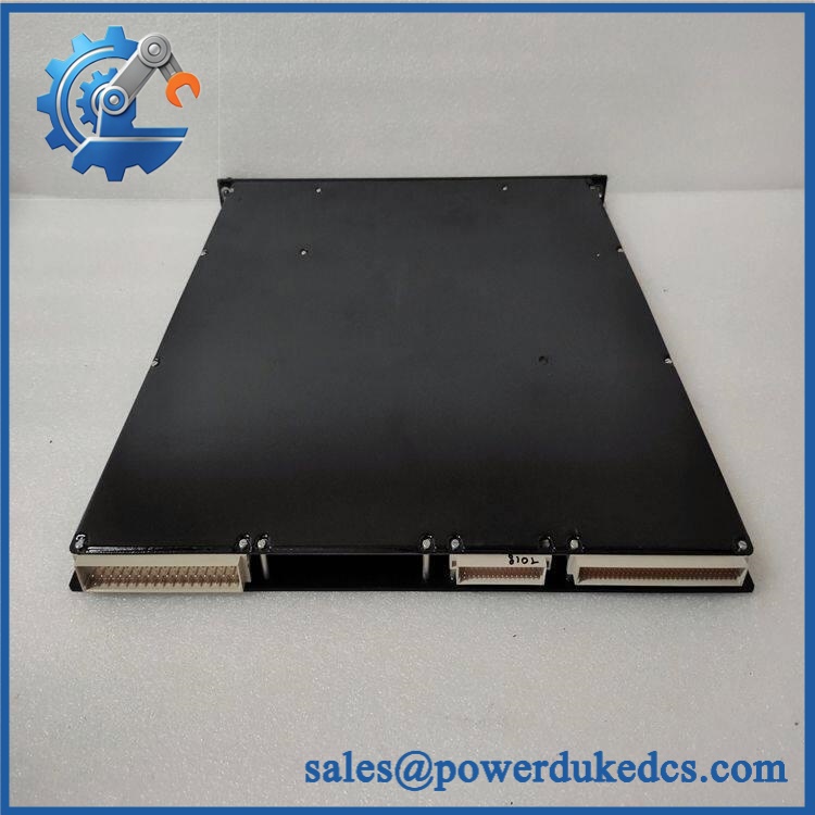
TRICONEX 3805E
Module 4: Application Scenarios & Field Realities
- For modulating control valves and I/P converters, 3805E provides an industry-standard 4-20 mA command path within the Tricon control architecture. Output scaling and final-element characteristics must match the application configuration.
- When the loop resistance is high, the external power calculation becomes critical. Cable resistance, valve positioner impedance, safety barriers, and additional series components all contribute to the total loop burden. A cabinet test at short cable length may pass while the installed field loop remains voltage-limited.
- For process loops using diagnostic overrange, the approximate 21.2 mA upper capability provides limited signal headroom above the nominal 20 mA span. The application must distinguish this region from the normal process measurement range.
- During replacement of an existing analog-output channel, measure the actual output at both the module and the receiving device. A correct 20 mA reading at the cabinet does not prove that the field actuator is receiving the required voltage under load.
Module 5: Migration, Compatibility & Installation Traps
Replacement Matrix
Replacement classification: Drop-in Replacement when the existing Tricon system uses the same 3805E configuration, compatible termination hardware, external loop-power arrangement, field wiring, and supported system revision.
Software compatibility: Configuration verification required. Channel assignments, engineering units, output scaling, alarm limits, diagnostic behavior, and application logic must correspond to the existing Tricon configuration.
Cross-model replacement: Hardware and load verification required. The 3805E is the standard 4-20 mA analog-output module. Other Tricon analog-output models can use different current ranges, load capabilities, isolation arrangements, or field-power architectures.
Field Traps — Watch Out
1. Do not size the loop supply from the nominal 24 V figure alone. The actual required voltage depends on total loop resistance. At higher resistance, the receiving device may not receive sufficient voltage even though the module’s PWR indication appears normal.
2. PWR1/PWR2 indications are not end-to-end loop verification. These indicators confirm the presence of loop power at the module-side monitoring point. They do not prove that adequate voltage remains at the field device under operating load.
3. The output returns are commoned. The eight channels are not individually isolated. A project requiring galvanically independent analog-return circuits needs a different architecture or additional isolation hardware.
4. Verify the receiving device before applying 20 mA. Confirm input impedance, polarity, permitted current range, and required compliance voltage for the connected positioner, controller, or converter.
5. Consider inductive load behavior. A 4-20 mA output connected to an actuator or positioner may interact with suppression components and long field cables. Static resistance measurement alone does not completely characterize the installed loop.
Module 6: Quality Assurance SOP
Pre-Shipment Inspection Protocol for TRICONEX 3805E
- OEM identity inspection: Verify Triconex/Invensys marking, exact 3805E designation, hardware revision, serial number, front-panel markings, and additional assembly identifiers.
- Variant verification: Confirm the unit is 3805E, not 3805H, 3806E, or another Tricon analog-output model.
- Mechanical inspection: Examine the housing, module guides, locking mechanism, backplane interface, connector surfaces, status LEDs, and accessible PCB areas for corrosion, contamination, deformation, cracked components, or unauthorized repair.
- Connector inspection: Check all module and termination interfaces for oxidation, bent contacts, damaged housings, loose hardware, or contamination.
- Power-on self-test: Install the module in a compatible Tricon test chassis and verify PASS, FAULT, ACTIVE, LOAD, PWR1, and PWR2 indications.
- Eight-channel verification: Exercise all 8 analog-output channels independently under controlled laboratory conditions.
- Loop-power verification: Apply a controlled 24 VDC external loop supply and confirm correct module-side power indication.
- Current-output calibration test: Measure representative output points at 4 mA, intermediate values, 20 mA, and the overrange region around 21.2 mA using calibrated equipment.
- Accuracy verification: Compare measured output against traceable current standards and evaluate compliance with the applicable accuracy specification over the intended temperature range.
- Resolution verification: Exercise representative output increments and verify expected 12-bit command behavior.
- Load sweep: Test the analog outputs against representative loop resistances and verify stable current regulation under increasing loop burden.
- Receiving-device simulation: Connect precision loop loads or representative positioner interfaces and verify that the commanded current remains within tolerance at the receiving end.
- Loop-power indicator verification: Verify PWR1 and PWR2 behavior under controlled loop-power presence and loss conditions while separately measuring actual load-side voltage.
- Channel-failure verification: Where the test environment permits, simulate a suitable internal channel fault and verify the expected TMR fault response and output-path behavior.
- Diagnostic verification: Check LOAD and other available diagnostic indications under controlled normal and abnormal conditions.
- TMR verification: Where the laboratory system permits, validate the three internal processing paths and confirm correct voted output behavior.
- Thermal observation: Operate multiple channels under representative loads for an extended interval and monitor for abnormal temperature rise, current drift, intermittent diagnostics, or output instability.
- Final QC record: Record exact model, revision, serial number, test chassis, loop-power voltage, all 8 channel results, calibration measurements, load values, diagnostic results, fault-response results, test duration, and inspector approval.
- ESD-controlled packaging: Place the module in an ESD-safe package and protect connectors, locking hardware, front-panel indicators, and PCB surfaces against impact, moisture, contamination, and electrostatic discharge.
Procurement note: The technically supported identity is TRICONEX 3805E — 8-point TMR Analog Output Module. Its key characteristics are 4-20 mA nominal output, approximately 21.2 mA overrange capability, 12-bit resolution, less than 0.25% FSR accuracy from 0°C to 60°C, commoned returns, external 24 VDC loop power, and load-dependent voltage requirements. The module should be evaluated together with the complete field loop, including the termination arrangement, power source, cable resistance, and receiving device.











 Start Chat


