

Description
- Brand Triconex / Invensys
- Full Model Number 4000093-310
- System/Series Family Tricon I/O Termination and Field Wiring System
- Core Function External termination cable linking compatible Tricon input termination assemblies to the corresponding I/O modules
- Top 3 Hardcore Specs Input cable assembly | Used with multiple Tricon termination-panel models | 310 cable designation
- Stock Status New Surplus — verify mating termination panel, module type, connector revision, and cable length before shipment
Module 3: Technical Product Introduction
A termination cable can become the hidden failure point in an otherwise healthy Tricon I/O channel. Triconex 4000093-310 is an input cable assembly used between specified Tricon external termination assemblies and the associated I/O module. Tricon technical documentation provides a direct part-number cross-reference: 9553-610, 9563-810, 9563-910, 9566-710, and 9566-810 termination-panel configurations are paired with cable 4000093-310. This makes the cable a defined system interconnect rather than a generic multiconductor replacement.
The exact mating hardware should be established before procurement. The Tricon guide distinguishes input cable families by termination-panel model, using 4000093-110, 4000093-210, and 4000093-310 for different assemblies. A replacement cable therefore needs to preserve connector type, pin assignment, channel mapping, and required physical reach. Secondary listings describe 4000093-310 as an external input terminal cable assembly, but published cable construction details vary substantially; engineering acceptance should therefore rely on the original Tricon termination documentation and the physical assembly being replaced.
Module 4: Application Scenarios & Field Realities
- Inside a Tricon I/O cabinet, 4000093-310 carries the field termination signals between a compatible external termination assembly and the Tricon I/O module. Connector engagement and correct pin mapping are more important than the cable’s appearance.
- When troubleshooting multiple simultaneous input faults, inspect the common cable path before replacing several I/O cards. A loose connector, damaged conductor group, or incorrect cable part number can affect numerous channels at once.
- For cabinets using 9553-610 or 9563-series termination hardware, 4000093-310 is explicitly identified in the Tricon part-number cross-reference. The same cable is also associated with the 9566-710 and 9566-810 termination-panel models.
- During a shutdown replacement, photograph both cable ends before removal and record the termination-panel model. A cable that physically reaches the rack can still be the wrong electrical assembly if its pinout or intended termination-panel family differs.
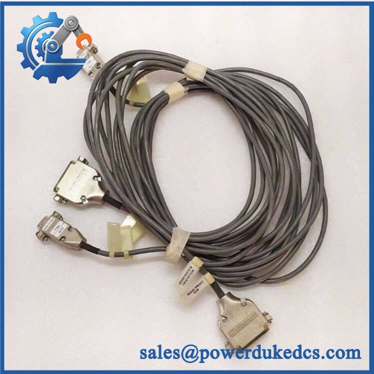
Triconex 4000093-310
Module 5: Migration, Compatibility & Installation Traps
Replacement Matrix
| Replacement Status | Engineering Assessment |
|---|---|
| Drop-in Replacement | Yes, when replacing 4000093-310 with the same cable assembly between the same approved Tricon termination-panel and I/O-module configuration. |
| Software Compatible | Not applicable. This is passive interconnect hardware with no user firmware or application software. |
| Hardware Modification Required | Normally no for an exact cable replacement. Modification may be required when changing termination-panel families, connector generations, routing, or cable length. |
⚠️ Field Traps: Watch Out
Do not substitute by connector appearance alone. Tricon documentation assigns different cable numbers to different termination-panel models. For example, 9553-610 and 9563-810 use 4000093-310, while 9552-610 and 9562-810 use 4000093-210. The cable number is therefore part of the electrical interface definition.
Verify the complete termination-panel model. The current Tricon cross-reference associates 4000093-310 with several distinct panel numbers, including 9553-610, 9563-810, 9563-910, 9566-710, and 9566-810. Confirm the cabinet drawing and panel label before shipment.
Do not infer cable length from “310.” The -310 suffix is a Tricon cable part-number designation, not sufficient evidence by itself for a 3.10 m or 310 cm physical length. Confirm the actual assembly length from the installed cable or controlled manufacturer documentation.
Inspect both connectors, not just the cable jacket. A connector can have internal contact damage while the outer shell remains intact. High-resistance or intermittent contacts can produce intermittent I/O faults that disappear during a basic continuity check.
Preserve cable routing and separation. Input cables in a safety cabinet should follow the approved routing and separation requirements. Excessive bending, compression at cabinet doors, or routing adjacent to high-energy conductors can introduce intermittent electrical problems.
Module 6: Quality Assurance SOP
4000093-310 should be accepted as a complete Tricon input interconnect assembly, with particular attention to connector integrity and pin-to-pin continuity.
- OEM anti-counterfeit visual inspection: Verify Triconex/Invensys identification, exact 4000093-310 marking where present, connector bodies, cable construction, labels, and manufacturing identifiers against controlled references.
- Part-number and traceability check: Record the complete cable number, available serial or batch information, termination-panel model, mating I/O module, and measured physical length.
- Mechanical inspection: Examine both connectors, latch or locking features, backshells, strain reliefs, cable jacket, and conductor exits for cracking, deformation, corrosion, contamination, or unauthorized repair.
- Connector contact inspection: Check contact alignment, retention, plating condition, and evidence of overheating or arcing before mating the cable to test hardware.
- Pin-to-pin continuity test: Verify every designated conductor from one connector end to the corresponding contact at the opposite end against the approved cable pinout.
- Pin-isolation test: Confirm no unintended continuity exists between adjacent signal conductors, shield connections, or designated isolated circuits.
- Insulation verification: Perform the applicable insulation-resistance test using the approved laboratory method and voltage appropriate to the cable assembly.
- Contact-resistance test: Measure representative contact pairs and investigate any abnormal or unstable resistance that could indicate connector wear.
- Termination-panel compatibility check: Confirm that the cable number matches the installed external termination model. Tricon documentation specifically pairs 4000093-310 with 9553-610, 9563-810, 9563-910, 9566-710, and 9566-810.
- Mating test: Connect the cable to representative approved Tricon termination and I/O hardware and confirm full mechanical engagement without excessive insertion force.
- Channel-mapping verification: Compare cable pin assignments with the cabinet wiring drawing and confirm that the expected field points arrive at the intended I/O channels.
- Continuity-under-movement test: While monitoring representative conductors, apply controlled cable movement near each connector and strain-relief point to identify intermittent opens or contact instability.
- System recognition test: Confirm the associated Tricon I/O module reports the expected field states through the installed termination and cable path.
- Communication handshake verification: The cable itself has no protocol engine; verify communication and I/O data transfer through the complete termination assembly → 4000093-310 → Tricon I/O module path.
- Signal-integrity verification: Apply representative discrete input conditions at the termination assembly and confirm that the correct Tricon channels respond without cross-channel activation.
- Extended-run test: Maintain representative signal activity while monitoring for intermittent state changes, diagnostic events, connector heating, or communication loss.
- Final QC record: Document exact cable number, termination-panel compatibility, measured length, pin-to-pin continuity, insulation result, contact inspection, channel mapping, mating test, system-level I/O verification, traceability, and packaging status.
Technical Identification Note: The Tricon Technical Product Guide explicitly identifies 4000093-310 as an input cable in its termination-panel cross-reference. It is paired with 9553-610, 9563-810, 9563-910, 9566-710, and 9566-810 termination-panel models, while other termination panels use different 4000093 cable numbers. Because secondary supplier pages publish inconsistent construction and length specifications, the safest procurement practice is to retain the exact 4000093-310 part number and verify both mating assemblies before shipment.











 Start Chat


