

Description
- Brand: TRICONEX
- Full Model Number: 4000093-320
- System/Series Family: Tricon safety controller field I/O and external termination architecture
- Core Function: Prefabricated digital-input cable assembly connecting Tricon input I/O to the associated external termination hardware
- Top 3 Hardcore Specs: 5 m installation length; digital-input prefabricated cable; Tricon external-termination interface
- Stock Status: Verify current New Surplus, Factory Sealed, or Fully Tested Refurbished condition before order
Module 3: Technical Product Introduction
A field-input fault is not always caused by the Tricon I/O module itself. In a distributed cabinet, the cable between the controller-side I/O interface and the external termination assembly becomes part of the signal path, and an intermittent conductor or connector can mimic an input-module problem. TRICONEX 4000093-320 is identified in current Triconex inventory records as a cable assembly, while an industrial procurement record identifies the exact part as a DI prefabricated cable for the TS3000/TRICON system with a 5-meter length.
The practical advantage is controlled field termination rather than a configurable electronics function. Public sources consistently classify 4000093-320 as a Triconex cable assembly, but detailed primary-source electrical data for the exact assembly—including conductor gauge, shielding construction, connector pinout, and environmental rating—was not located in the available public documentation. For procurement, the strongest verified dimensional information is the 5 m cable length reported in the TS3000/TRICON material record.
Module 4: Application Scenarios & Field Realities
- In Tricon TS3000 installations using external digital-input termination, the 4000093-320 is used as a prefabricated DI connection between the controller-side interface and the field termination architecture. The 5-meter length is particularly useful where the termination location is separated from the main rack.
- During brownfield cabinet maintenance, replacing the cable can be preferable to disturbing individual field conductors when the original prefabricated wiring arrangement is still documented. The correct strategy is to reproduce the original cable route, connector orientation, and termination assignment—not simply install any cable that reaches between the two panels.
- Where several Tricon cable assemblies are installed together, part-number control becomes important. Current Triconex listings distinguish 4000093-320 from nearby cable numbers such as 4000093-310 and 4000094-310. Treat those as separate assemblies unless the cabinet drawings explicitly establish interchangeability.
- When diagnosing intermittent digital-input states, test the cable assembly as part of the complete path. Continuity at rest is not enough; intermittent opens can appear only when the connector is under mechanical stress or when the cable is moved. A controlled continuity and insulation test should therefore precede replacement of a healthy input module.
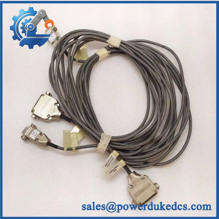
TRICONEX 4000093-320
Module 5: Migration, Compatibility & Installation Traps
Replacement Matrix
Exact 4000093-320 5 m assembly with matching Tricon termination architecture: Drop-in Replacement
When the installed system uses the same 4000093-320 assembly and the connector arrangement, cable route, field termination, and controller configuration all match, replacement can normally be performed without software changes.
4000093-320 replaced by another 4000093-series cable: Hardware Verification Required
Nearby model numbers are listed as separate Triconex cable assemblies. Do not assume equal pin assignment, cable length, connectorization, or application solely from the shared 4000093 prefix.
Generic multicore control cable substituted for 4000093-320: Hardware Modification Required
A generic cable may reproduce continuity while failing to reproduce the intended connector, conductor assignment, shielding, mechanical retention, or factory termination arrangement. An engineered equivalency review is required before substitution.
⚠️ Field Traps (Watch Out)
Length trap: The available TS3000/TRICON procurement record specifies 4000093-320 as a 5-meter DI prefabricated cable. Do not order a cable from the part number alone without checking the installed route and actual required length.
Part-number confusion: 4000093-320, 4000093-310, and 4000094-310 appear as separate Triconex cable assemblies in current product indexes. One nearby part is explicitly described as an external terminal cable assembly, so suffix-level identification matters.
Pinout verification trap: Public listings do not provide a sufficiently authoritative pinout for 4000093-320. Do not infer conductor mapping from a visually similar Tricon cable. Compare the actual connector markings with the approved cabinet wiring diagram before reconnecting the assembly.
Mechanical-routing trap: A 5-meter cable should be routed with controlled bend radius and separated from high-noise power conductors where practical. A cable can pass a static continuity test and still create intermittent digital-input faults when installation stress or electromagnetic interference is present.
Module 6: Quality Assurance SOP
Pre-Shipment QA Protocol for TRICONEX 4000093-320
- Step 1 — Identity Verification: Confirm TRICONEX marking, 4000093-320 part number, cable length, available batch information, connector markings, and associated cabinet/termination reference.
- Step 2 — OEM Anti-Counterfeit Visual Inspection: Inspect cable markings, connector housings, molded identification, strain reliefs, termination quality, and evidence of unauthorized rework.
- Step 3 — Mechanical Inspection: Examine the full cable for cuts, abrasion, crushed sections, jacket cracking, connector deformation, damaged contacts, loose strain relief, or excessive bending.
- Step 4 — Length Verification: Measure the complete assembly and verify the nominal 5 m configuration against the purchasing specification and installed cabinet requirement.
- Step 5 — Pin-to-Pin Continuity Test: Verify every conductor against the approved Triconex cable drawing or cabinet wiring documentation.
- Step 6 — Cross-Connection Test: Check for unintended shorts, swapped conductors, open circuits, and incorrect shield or common connections.
- Step 7 — Insulation Resistance Test: Where appropriate for the cable assembly and test fixture, check conductor-to-conductor and conductor-to-shield insulation resistance at a controlled test voltage suitable for the connected hardware.
- Step 8 — Connector Fit Verification: Mate both ends with approved Tricon test interfaces and confirm complete seating, retention, correct keying, and absence of excessive insertion force.
- Step 9 — I/O Path Verification: Connect the cable to a compatible digital-input test arrangement and verify that simulated input states are transferred correctly from the field-termination side to the controller-side interface.
- Step 10 — Final QC Record: Record complete part number, measured length, connector identification, continuity results, insulation result, I/O-path test result, visual condition, test date, and final QC disposition.
Technical Verification Note: Current Triconex product indexes consistently identify 4000093-320 as a cable assembly. A separate TS3000/TRICON procurement record identifies the exact part as a DI prefabricated cable and specifies a 5-meter length. Publicly available sources do not establish a sufficiently authoritative exact pinout, conductor gauge, or shield construction for this part, so those details should be taken from the installed Tricon cabinet documentation rather than inferred from reseller catalogs.











 Start Chat


