

Description
- Brand: TRICONEX
- Full Model Number: DO 3626X / 3626X
- System/Series Family: Tricon CX I/O Expansion Chassis
- One-Sentence Core Function: 32-point TMR supervised or non-supervised digital output module for 24 VDC field loads
- Top 3 Hardcore Specs: 32 commoned outputs; 20.4–28.8 VDC recommended range; 1.70 A ±10% maximum per point
- Stock Status: New Surplus / Fully Tested Refurbished — verify Tricon CX chassis, termination kit, and supervision configuration before shipment
Module 3: Technical Product Introduction
A field-output fault is especially difficult to diagnose when the actuator, wiring, termination panel, and output switch all remain possible failure points. The TRICONEX DO 3626X is a 32-point TMR digital output module developed for the Tricon CX platform. The Tricon CX technical specification identifies it as a supervised or non-supervised digital output module, with commoned outputs intended for both energize-to-trip and de-energize-to-trip applications. It is installed only in a Tricon CX I/O expansion chassis.
The documented electrical range is 20.4–28.8 VDC, with 24 VDC nominal and 28.8 VDC maximum usable voltage; 32 VDC is listed as the maximum over-voltage range. Each point is rated at 1.70 A ±10% maximum, with a 5 A surge for 7 ms, while total output current is limited to 10 A per termination panel and 20 A per module. The module itself consumes less than 8 W of logic power. Output switches provide protection against over-voltage, over-temperature, over-current, and reverse EMF, eliminating the need for a field fuse at the compatible termination panel.
Module 4: Application Scenarios & Field Realities
- At ESD final elements and 24 VDC shutdown actuators, the 3626X provides the TMR output path from the Tricon CX logic to the field load. Its 32-point architecture suits dense discrete-output sections where solenoids, annunciators, and interlock devices share a cabinet area.
- When a commanded output does not reach the expected field state, do not immediately replace the DO card. The 3626X incorporates voltage and current loopback diagnostics, while supervised points can be configured to detect field-circuit faults. Checking the termination panel and field supply alongside the module gives a much cleaner fault isolation path.
- For installations using line-fault detection, the termination hardware matters. Tricon CX documentation identifies 9662X-610RF and 9671X-610RF termination options, with the latter supporting supervised commoned 24 VDC applications. Each termination panel supports 16 points, so a 32-point 3626X requires two panels in that arrangement.
- During a cabinet migration, do not assume that a legacy Tricon output module can replace the 3626X simply because it also switches 24 VDC. The 3626X is designed specifically for Tricon CX I/O expansion chassis, and its termination architecture is part of the platform design.
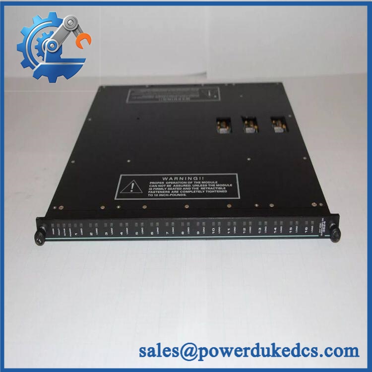
TRICONEX DO 3626X
Module 5: Migration, Compatibility & Installation Traps
Replacement Matrix
| Replacement Type | Assessment |
|---|---|
| Drop-in Replacement | Yes, for an exact 3626X replacement within a compatible Tricon CX I/O expansion chassis |
| Software Compatible | Conditional — verify Tricon CX system revision, point supervision settings, application configuration, and I/O database |
| Hardware Modification Required | Normally no for an exact replacement; termination kit, cable, field-power arrangement, and chassis must match |
⚠️ Field Traps — Watch Out
1. Tricon CX chassis compatibility is mandatory.
The technical guide states that 3626X modules can be installed only in Tricon CX I/O expansion chassis. Do not treat the 3626X as a direct replacement for an earlier Tricon 3625/3625A simply because both use 24 VDC outputs.
2. The 3626X uses 16-point termination panels.
Although the module has 32 output points, the documented termination options are 16-point panels. Depending on the selected termination kit, two panels may be required for one module.
3. Supervised and non-supervised configurations require different engineering checks.
Point supervision can be programmed individually, and open/short detection thresholds are programmable for supervised points. Preserve the existing application configuration rather than assuming every 3626X installation uses the same diagnostic mode.
4. Keep the field-power source arrangement under control.
The documented module specification provides 10 A maximum per termination panel and 20 A maximum per module. The field-load calculation therefore needs to cover the aggregate demand, not simply the current of an individual solenoid.
Module 6: Quality Assurance SOP
- OEM anti-counterfeit visual inspection — inspect TRICONEX identification, 3626X model marking, dark-blue color code, status indicators, connectors, housing, and visible manufacturing details.
- Exact part-number verification — confirm DO 3626X / 3626X against the purchase order and physical module label.
- Platform verification — confirm the target installation uses a Tricon CX I/O expansion chassis, since the documented 3626X installation is restricted to that platform.
- Termination verification — identify the installed termination arrangement and confirm compatibility with 9662X-610RF or 9671X-610RF, as applicable. Verify whether one or two 16-point panels are required.
- Mechanical inspection — examine the backplane connector, field-interface connectors, locking features, PCB surfaces, housing, and mounting interfaces for bent contacts, corrosion, contamination, cracks, or impact damage.
- Power-on self-test (POST) — energize the module in an approved Tricon CX test chassis and record PASS, FAULT, ACTIVE, and LOAD indications, current behavior, and abnormal temperature rise.
- 32-channel output simulation — operate representative output points with controlled loads at the documented 24 VDC operating conditions and verify commanded ON/OFF states.
- Full-channel verification — where the laboratory fixture permits, test all 32 outputs independently. Record commanded state, field voltage, load current, loopback state, and diagnostic result.
- Output-limit verification — validate representative channels against the documented 1.70 A ±10% per-point maximum, while maintaining aggregate load below the applicable 10 A per termination-panel / 20 A per-module limits.
- Loopback verification — verify the voltage and current loopback circuits on representative channels and confirm that controlled output or field faults generate the expected diagnostic response.
- Supervision verification — for supervised applications, use an approved fixture to simulate defined open- and short-circuit conditions and confirm the configured detection response.
- Termination-path verification — perform point-to-point continuity checks through the applicable termination panel and cable, preserving the 1–16 / 17–32 channel mapping.
- TMR verification — integrate the module with compatible Tricon CX processor and I/O hardware and verify triplicated output processing, diagnostics, and stable operation.
- Communication handshake verification — verify module communication through the complete Tricon CX architecture. This is a system-level I/O verification, not a standalone Ethernet or serial test.
- Final QC and packaging — record model number, hardware revision, termination configuration, 32-channel test results, supervision status, diagnostic results, photographs, ESD protection, and packaging condition.
Engineering note: The TRICONEX DO 3626X is documented as a 32-point commoned TMR digital output module for Tricon CX I/O expansion chassis. The published specification gives a 20.4–28.8 VDC recommended operating range, 24 VDC nominal voltage, 1.70 A ±10% maximum per point, 5 A surge for 7 ms, 10 A maximum per termination panel, and 20 A maximum per module. Compatible termination options include 9662X-610RF and 9671X-610RF, with 16 points per termination panel.











 Start Chat


