

Description
- Brand: Triconex
- Full Model Number: DO2401 / 7400209-030
- Lifecycle Status: Legacy / Obsolescence-Risk
- Core Function: Digital output baseplate for Triconex safety instrumented systems
- Top 3 Technical Specs: 24 output channels; 24 VDC rating; 2 A channel rating
- Stock & Condition: New surplus / tested inventory — verify system generation, terminal arrangement, and associated output hardware before PO
Current commercial references identify DO2401 / 7400209-030 as a Triconex Digital Output Baseplate, with 24 channels and published ratings of 24 VDC and 2 A per channel. Physical dimensions and weight vary slightly between listings, so the nameplate and actual assembly should control final procurement data.
Module 3: Obsolescence & Supply Chain Deep Dive
A failed DO2401 can affect multiple safety-related output circuits simultaneously because the baseplate provides the physical output interface for a high-density Triconex installation. With 24 output channels, a single failed assembly can disrupt commands to valves, relays, actuators, alarms, or other field devices. That makes rapid identification important during an emergency replacement — especially where the SIS remains partially operational but one output group has become unreliable. Current equipment references consistently identify 7400209-030 / DO2401 as a digital-output baseplate rather than a standalone processor module.
The TCO case favors replacing the exact baseplate when the Triconex control architecture remains serviceable. Existing field wiring, output devices, system logic, and commissioned safety configuration can remain substantially unchanged, avoiding a larger SIS modification project. The procurement risk is configuration accuracy: this item is a baseplate/interface assembly, so it should not be confused with the digital-output electronic execution hardware installed with it. Verify the complete assembly, terminal arrangement, system revision, and associated output hardware before release (particularly where outputs participate in ESD or other protective actions).
Module 4: Compatibility & Replacement Matrix
| Procurement Check | DO2401 7400209-030 Assessment | Engineering Action |
|---|---|---|
| Replacement Type | Drop-in Replacement for a matching DO2401 installation | Match complete part number and physical configuration |
| Software Compatibility | Configuration-dependent at system level | Verify Triconex system configuration and associated output hardware |
| Hardware Modification | Normally none for an exact replacement | Confirm terminals, connectors, mounting, and field wiring |
| Typical Switch Time | Approx. 1–3 hours | Allow additional time for loop and output verification |
| Estimated Engineering / Testing Cost | Approx. 400–1,500 | Include output-loop and safety-function checks |
| Alternative | Different digital-output baseplate or architecture | Requires documented engineering review |
Field Traps — Watch Out
Baseplate versus output electronics: The is described commercially as a Digital Output Baseplate. Do not assume that replacing the baseplate alone replaces the associated digital-output electronic hardware. Verify what failed and what is included in the quoted assembly.
Output rating verification: Published commercial specifications identify 24 VDC and 2 A per channel. Those figures should not be treated as universal acceptance limits for every connected load. Confirm the actual load type, protection circuitry, fusing, and approved Triconex installation documentation before switching field circuits.
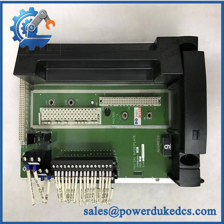
TRICONEX DO2401 7400209-030
Module 5: Quality Assurance & Testing SOP
The should be treated as a safety-system interface component, with mechanical, electrical, and controlled output testing completed before release.
1. Incoming inspection
- Record manufacturer, complete part number, serial/date code, and revision markings.
- Perform OEM anti-counterfeit visual inspection.
- Inspect baseplate housing, terminal interfaces, connectors, mounting points, and internal contacts.
- Check for corrosion, contamination, deformation, cracked insulation, damaged terminals, or evidence of unauthorized modification.
2. Configuration verification
- Confirm / 7400209-030 identification.
- Record all hardware and revision markings.
- Verify the 24-channel output configuration.
- Confirm terminal arrangement against the customer’s installed system.
- Identify the associated Triconex digital-output electronic assembly.
- Photograph identification labels and terminal interfaces for traceability.
3. Electrical inspection
- Perform continuity checks on applicable output paths.
- Verify terminal-to-terminal isolation where applicable.
- Inspect connector contacts and retention.
- Check grounding and protective bonding according to the approved procedure.
- Perform controlled insulation-resistance testing on applicable circuits.
- Check for unintended shorts between output channels and ground.
4. Power-on and output testing
- Install the baseplate in a compatible Triconex test configuration.
- Install the associated digital-output hardware.
- Apply controlled system power.
- Perform power-on self-test (POST) at the system level.
- Verify normal hardware recognition and diagnostic status.
- Exercise representative digital-output channels.
- Verify correct ON/OFF state transmission.
- Measure output voltage and current under controlled loads.
- Test representative loads without exceeding approved channel limits.
- Perform I/O load testing across required output channels.
- Run repeated switching cycles to identify intermittent terminals or unstable connections.
5. Final QC
- Record channel-test results, load conditions, continuity measurements, revision, serial number, and test date.
- Confirm terminal configuration against the purchase specification.
- Generate a unit-specific Test Report.
- Verify connector and mounting integrity.
- Package using appropriate electrical and mechanical protection.
- Apply final QC identification before shipment.
Module 6: Procurement & Lifecycle FAQ
Is TRICONEX 7400209-030 genuinely in stock, and what is the emergency-shipping cutoff?
Current commercial listings show / 7400209-030 offered as new stock, with one listing reporting inventory and another reporting a 1–3 day delivery window after payment. Actual allocation should still be confirmed against the physical unit before PO release. Emergency dispatch depends on QC completion, payment clearance, warehouse processing, and the courier cutoff.
How do you guarantee the condition and authenticity of surplus units?
Require complete part-number and revision verification, terminal and connector inspection, continuity and isolation checks, controlled system power-up, representative digital-output testing, load testing, and a unit-specific Test Report. The actual assembly should be photographed before shipment and tied to its serial or identification markings.
Are there any firmware compatibility issues I should warn my engineers about before issuing the PO?
The baseplate itself is primarily a hardware interface, so the critical compatibility issue is the associated Triconex output electronics and system configuration, rather than firmware inside the baseplate. Engineers should verify the controller/system generation, output module pairing, terminal assignments, field-load characteristics, and existing safety configuration before replacement.
Can I substitute another Triconex digital-output baseplate?
Not automatically. Similar baseplates can differ in channel arrangement, terminal configuration, mechanical interfaces, or associated output hardware. Match / 7400209-030 to the installed assembly and verify the complete output path before approval.
What warranty and return terms should procurement require?
Specify / 7400209-030, serial number, revision, tested condition, associated output hardware, warranty period, DOA criteria, acceptance window, and return procedure in the PO. Functional acceptance should include baseplate continuity, system recognition, representative output-channel operation, and controlled load testing before the safety loops are returned to service.











 Start Chat


