

Description
- Brand Triconex / Invensys
- Full Model Number DO3625A / Model 3625A
- System/Series Family Tricon v10.2 and later Safety Instrumented System
- Core Function TMR supervised or non-supervised digital output switching for 32 commoned 24 VDC field points
- Top 3 Hardcore Specs 32 outputs | 16–32 VDC recommended range | 1.70 A ±10% maximum per point
- Stock Status New Surplus — verify hardware revision, termination panel, field-power grouping, and application configuration before shipment
Module 3: Technical Product Introduction
A failed output module can interrupt commands to shutdown solenoids, relays, alarms, or other final elements even when the Tricon processors remain healthy. Triconex DO3625A / Model 3625A is a 32-point TMR digital output module designed for nominal 24 VDC field circuits. It supports both supervised and non-supervised operation and can be programmed for energize-to-trip or de-energize-to-trip applications. Tricon documentation specifies that the 3625A can be installed only in Tricon v10.2 and later systems.
The defining hardware change from the 3625 is the field-power arrangement. On the 3625A, power is commoned in two groups of 16 points while the return remains common, with the separation implemented through the termination panels. Published specifications give a 16–32 VDC recommended range, 36 VDC maximum, 1.70 A ±10% maximum per point, and 5 A surge for 7 ms. The output switches are self-protected against over-voltage, over-temperature, and over-current, so field termination does not require individual output fuses.
Module 4: Application Scenarios & Field Realities
- In a Tricon emergency-shutdown cabinet, DO3625A can drive 24 VDC solenoids, relay interfaces, annunciators, and other discrete final-control circuits. Its 32-point capacity is useful for dense output requirements while retaining the Tricon TMR architecture.
- Where output-circuit supervision is required, individual points can be programmed for supervised operation, allowing the system to monitor field-circuit conditions rather than treating every output simply as an On/Off command. The documented design supports programmable short/open-circuit detection thresholds.
- For cabinets with substantial field loading, the 3625A’s 16-point power grouping matters. Unlike the original 3625 arrangement, the field supply is separated into two 16-point groups through the termination panels. A supply fault affecting one group therefore has a different scope from a fault on the fully commoned 3625 architecture.
- During an online maintenance event, the 3625A belongs to the Tricon architecture supporting hot-spare replacement and continuous diagnostics. The exact intervention sequence should follow the approved Tricon maintenance procedure; a physical module swap is not, by itself, proof that the safety function has been restored.
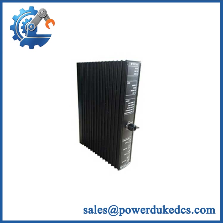
Triconex DO3625A
Module 5: Migration, Compatibility & Installation Traps
Replacement Matrix
| Replacement Status | Engineering Assessment |
|---|---|
| Drop-in Replacement | Yes, for a like-for-like 3625A installation in a compatible Tricon v10.2+ chassis using the correct 16-point commoned termination panels and approved field-power arrangement. |
| Software Compatible | Generally yes for an exact 3625A replacement, but point assignments, supervision settings, diagnostics, output logic, hardware revision, and approved Tricon configuration must be verified. |
| Hardware Modification Required | Normally no for an exact 3625A replacement. Modification may be required when replacing an older 3625 arrangement, changing termination hardware, or changing the field-power architecture. |
⚠️ Field Traps: Watch Out
The 3625A is not merely a relabeled 3625. Tricon documentation states that the 3625A separates field power into groups of 16 points while maintaining a common return, whereas the 3625 has field power commoned across all points. This difference must be reflected in the termination-panel wiring.
Verify the field-power source arrangement. Invensys recommends wiring the termination panels in parallel and powering them from a single set of redundant field-power sources. The 3625A can use four independent sources only when their voltages remain within 5% of the highest supplied voltage; otherwise, voter faults and alarms may occur even though the module continues operating.
Do not add unnecessary fuses to imitate an older output design. The 3625A output switches are documented as self-protected against over-voltage, over-temperature, and over-current, and the field termination specification states that output fuses are not required.
Respect the 1.70 A point rating. The published maximum is 1.70 A ±10% per output, while the total module output is limited by the termination-panel arrangement. Do not interpret the per-point rating as permission to draw that current simultaneously from every channel.
Check the Tricon software generation. The documentation states that Models 3625 and 3625A can be installed only in Tricon v10.2 and later systems. A physically compatible older chassis should not be assumed to accept the module.
Module 6: Quality Assurance SOP
A surplus DO3625A should be tested as a 32-channel TMR output assembly, including supervised-field diagnostics where the application uses that function.
- OEM anti-counterfeit visual inspection: Verify Triconex/Invensys identification, exact DO3625A / 3625A marking, dark-blue identification stripe, PCB revision, front-panel labels, connector geometry, and manufacturing identifiers against controlled references.
- Part-number and traceability check: Record the complete model number, hardware revision, serial number, date code, and associated termination-panel information.
- Mechanical inspection: Examine the backplane connector, ejectors, enclosure, PCB, field interface, and locking/keying features for bent contacts, corrosion, contamination, cracking, or unauthorized repair.
- Power-on self-test (POST): Install the module in an approved Tricon test chassis and verify expected PASS, FAULT, ACTIVE, and LOAD diagnostic indications.
- 24 VDC supply verification: Apply a controlled field supply within the documented 16–32 VDC recommended range, without exceeding the 36 VDC maximum.
- 32-channel functional test: Exercise every output individually and verify clean On/Off transitions into controlled loads.
- Output-current test: Test representative channels below the 1.70 A ±10% maximum per-point rating, monitoring output voltage, current, and thermal behavior.
- Surge-response verification: Where the approved fixture permits, apply controlled inrush conditions consistent with the documented 5 A surge for 7 ms characteristic.
- Minimum-load verification: Confirm representative loads satisfy the documented 10 mA minimum required load for the applicable output configuration.
- Leakage-current test: Measure Off-state leakage and verify it remains within the documented maximum of 2.0 mA at 24 VDC and 2.5 mA at 32 VDC.
- Supervision test: For supervised points, use the approved field termination arrangement and confirm short/open-circuit detection at the configured threshold.
- Output diagnostic test: Exercise voltage and current loopback diagnostics and verify detection of controlled output-switch or field-circuit faults.
- Power-group verification: Test the two 16-point field-power groups independently and confirm that the termination architecture matches the 3625A design rather than the fully commoned 3625 arrangement.
- Isolation verification: Test system-to-field isolation according to the approved procedure, using the documented 1,500 VDC minimum isolation specification as the reference.
- TMR verification: Test the module in the complete three-channel architecture and confirm correct voted output behavior and diagnostic response to an approved single-channel fault.
- Termination-panel verification: Confirm the correct 16-point commoned termination panel arrangement and field-power source configuration before applying production voltage.
- System recognition test: Verify module recognition, point addressing, output status, diagnostics, and data exchange through the Tricon I/O architecture.
- Communication handshake verification: Confirm successful output-command transfer between the Tricon processors and DO3625A, together with correct diagnostic reporting. The itself is an I/O module rather than a standalone Ethernet or Modbus interface.
- Fault-injection test: Apply controlled open/short or output-fault conditions permitted by the applicable maintenance procedure and verify the intended diagnostic response.
- Extended-run test: Operate representative channels continuously under controlled loads while monitoring output stability, current, temperature, field alarms, and intermittent faults.
- Final QC record: Document hardware revision, supply voltage, all 32 output results, current measurements, leakage, supervision diagnostics, power-group verification, isolation result, TMR behavior, extended-run observations, traceability, and packaging condition.
Technical Identification Note: Tricon documentation identifies 3625A as a 32-point TMR supervised or non-supervised 24 VDC digital output module intended for Tricon v10.2 and later systems. Its recommended operating range is 16–32 VDC, with 36 VDC maximum, 1.70 A ±10% maximum per point, 5 A surge for 7 ms, and 1,500 VDC minimum system-to-field isolation. The defining architectural difference from 3625 is the separation of field power into two 16-point groups with a common return.











 Start Chat


