

Description
- Model: UNS4684A-P,V.1
- Part Number: HIEE305114R0001
- Brand: ABB
- Series / Platform: UNITROL 5000 / UNITROL 6000
- Part Type: PCB Assembly / Excitation System Board
- Core Function: Provides overvoltage protection and pulse-coupling functions within the excitation system.
- Key Specifications: V.1 hardware revision; PCB assembly; associated with ABB UNITROL excitation equipment; approximately 320 × 230 × 37 mm and 0.31 kg according to published supplier data.
- ABB Product Identification: ABB lists the catalog description as “UNS 4684a-P, V.1: PCB ASSEM.”
Product Introduction
A fault in an excitation-system protection circuit can quickly become a generator availability problem, particularly when the installed UNITROL system depends on legacy electronic assemblies. ABB UNS4684A-P,V.1 / HIEE305114R0001 is identified as a dedicated PCB assembly for ABB excitation-system equipment. ABB-related product records specify the catalog description as UNS 4684a-P, V.1: PCB ASSEM.
The board is associated with the UNITROL 5000 and UNITROL 6000 excitation-system family. Available technical descriptions identify its functional role with overvoltage protection (OVP) and pulse coupling, making it relevant to protection and control functions surrounding the generator excitation circuit.
For procurement, the complete identifier should be retained: UNS4684A-P,V.1 — HIEE305114R0001. ABB’s broader hardware listings contain numerous UNS-series boards with similar naming conventions, so matching only the UNS4684A-P family name is not sufficient for a replacement order.
Core Technical Specifications
| Parameter | Value |
|---|---|
| Manufacturer | ABB |
| Model | UNS4684A-P,V.1 |
| Part Number | HIEE305114R0001 |
| Product Type | PCB Assembly |
| Catalog Description | UNS 4684a-P, V.1: PCB ASSEM. |
| Functional Category | Excitation System Protection / Pulse Coupling |
| Associated System | UNITROL 5000 / UNITROL 6000 |
| Hardware Revision | V.1 |
| Functional Role | Overvoltage Protection / Pulse Coupling |
| Mounting | Subrack / Plug-in Assembly |
| Reported Dimensions | Approx. 320 × 230 × 37 mm |
| Reported Net Weight | Approx. 0.31 kg |
| Country of Origin | Switzerland, according to supplier catalog data |
| Minimum Order Quantity | 1 piece |
| Made to Order | No |
| Customs Tariff Number | 85371092 |
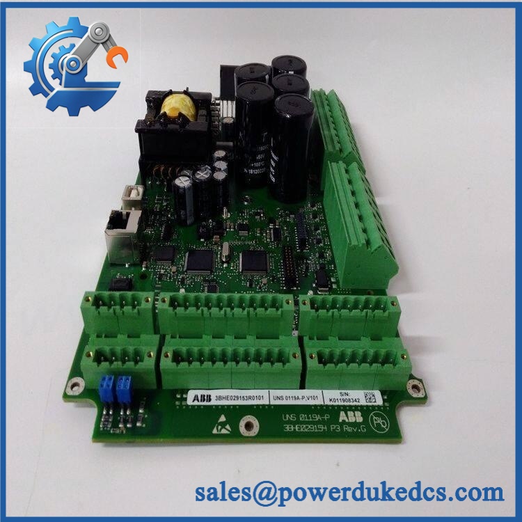
ABB UNS4684A-P,V.1 HIEE305114R0001
ABB-related catalog data confirms the model and PCB-assembly designation; dimensional, weight, origin, and tariff information are reported by aftermarket supplier records.
Application Scenarios & Pain Points
The technical priority with this board is maintaining the protection path of the excitation system, not simply restoring a generic PCB position.
1. Hydroelectric Generator Excitation
During rapid generator load changes, the excitation system can experience demanding transient conditions. The UNS4684A-P,V.1 is associated with the protection and pulse-coupling portion of the UNITROL architecture, where reliable electronic response is important.
2. Thermal Power Generation
For large turbine-generator sets, excitation-system protection has to remain available during abnormal electrical conditions. A failed protection PCB can therefore become a maintenance priority even when the main excitation controller remains operational.
3. Static Excitation Systems
In high-current static excitation equipment, protection of the excitation circuit becomes particularly important. Supplier technical descriptions associate the with applications involving high-current excitation systems.
4. Field Discharge and De-Excitation
During generator shutdown or emergency trip conditions, the excitation system must follow the configured de-excitation sequence. The associated pulse-coupling and protection circuitry should therefore be checked whenever this board is suspected of malfunctioning.
5. Legacy UNITROL Maintenance
For installations operating older UNITROL hardware, maintaining a verified spare PCB can shorten recovery time after an electronic failure. (A compatible board is considerably easier to deploy when the original configuration and revision information have already been documented.)
Common Error Codes & Diagnostic Symptoms
No dedicated numerical error-code table for HIEE305114R0001 was identified in the available product records. Diagnosis should therefore focus on protection behavior and board-level symptoms.
- Symptom/Code: Excitation-system overvoltage protection not responding correctly → Diagnosis: The OVP sensing or protection path associated with the PCB may have an internal circuit failure or connection problem → Action: Verify the external protection circuit and connections, then replace the board if the fault is isolated to the PCB.
- Symptom/Code: Pulse-coupling output missing or abnormal → Diagnosis: A failed coupling circuit, connector issue, or internal component fault can interrupt the required trigger-pulse path → Action: Check the associated pulse circuit and interface connections; replace the PCB when the hardware fault is confirmed.
- Symptom/Code: Repeated excitation protection alarm after external circuit checks → Diagnosis: If field wiring, sensing components, and the associated protection circuit test correctly, the ,V.1 may be the defective element → Action: Substitute with a verified HIEE305114R0001 and perform the applicable excitation-system functional test.
Cross-Reference & Lifecycle Migration
Related Identification
The primary identification pair is:
| Identifier | Description |
|---|---|
| ABB order/product number | |
| PCB assembly designation | |
| Short model designation |
ABB-related parts databases consistently associate with .
Compatibility
The board is associated with UNITROL 5000 / UNITROL 6000 excitation systems in available technical descriptions.
However, the UNITROL family contains numerous hardware assemblies and revisions. A board with a similar UNS designation should not automatically be considered a direct replacement. Check:
- Complete ABB part number
- V.1 revision
- Existing UNITROL system model
- Rack/subrack position
- Interface and connector arrangement
- Protection-system configuration
- Existing excitation-system documentation
Firmware / Configuration
This item is identified as a PCB assembly, rather than a standalone programmable controller. Public product information does not establish a universal firmware-flashing requirement for every replacement.
Where the installed UNITROL system contains configurable protection or pulse-coupling parameters, document the existing configuration before replacement and validate the protection sequence after installation.
Lifecycle Status
Lifecycle: Legacy / Mature
The ,V.1 belongs to an established UNITROL hardware platform. For plants with older UNITROL 5000/6000 equipment, maintaining a tested spare is useful for reducing extended downtime caused by electronic-board sourcing delays.
Field Engineer’s Tech Notes
Tech Note 1 — Do not test the protection board by defeating the protection circuit.
This board is associated with excitation-system protection. Never bypass an OVP or protection path simply to determine whether the generator can operate. Use the approved UNITROL test procedure and an appropriate simulation/test setup.
Tech Note 2 — Verify connector orientation before insertion.
The PCB is intended for a specific rack/subrack arrangement. Check guide rails, connector alignment, and mounting hardware before applying insertion force. (A damaged backplane connector can create a much larger repair than the original PCB fault.)
Strict QA & Testing SOP
A suitable inspection and testing process for should include:
- Part Number Verification
Confirm and against the physical identification. - Visual Inspection
Examine the PCB assembly for cracked components, corrosion, contamination, burnt areas, damaged connectors, and signs of previous repair. - Revision Verification
Record the V.1 hardware designation and all visible board-revision markings. - Dimensional Inspection
Compare the assembly with the published approximate 320 × 230 × 37 mm dimensions where applicable. - Connector Inspection
Check mating contacts, guide features, and connector housings for deformation or oxidation. - Component-Level Inspection
Examine protection components, coupling circuitry, capacitors, resistive networks, and visible semiconductor devices for physical abnormalities. - Controlled Electrical Test
Use an appropriate UNITROL-compatible test setup to verify the relevant protection and pulse-coupling circuits. Do not energize the board with an arbitrary supply. - Protection Function Test
Simulate the applicable input condition using a controlled test fixture and verify the expected protection response. - Pulse-Coupling Verification
Where the approved test equipment is available, verify the relevant coupling signal and output behavior. - Final QC Documentation
Record serial number, part number, revision, photographs, test conditions, and measured results. - ESD Packaging
Place the tested PCB in anti-static packaging with mechanical protection before shipment.
Test videos can be provided with the inspection record when required.
Buyer’s FAQ
A: Do not assume hot-swapping is permitted. This PCB is associated with excitation-system protection, so replacement should follow the applicable UNITROL shutdown, isolation, and commissioning procedure.
Q: Is ,V.1 the same as ?
A: Yes. is the model/designation associated with in the available ABB-related product records.
Q: Is this board used with UNITROL 5000 or UNITROL 6000?
A: Available technical references associate the ,V.1 with UNITROL 5000 and UNITROL 6000 excitation systems. Verify the installed system configuration before ordering.
Q: How can I verify a New Original unit?
A: Request photographs of the actual PCB, ABB identification markings, complete number, V.1 revision, packaging, and traceability information. For legacy excitation hardware, exact identification should be confirmed before purchase.











 Start Chat


