

Description
- Model: 07DC92 GJR5252200R0101
- Brand: ABB
- Series: Advant Controller 31 (AC31)
- Core Function: Handles configurable digital I/O signals
- Type: Digital I/O module
- Key Specs: 32 configurable digital I/Os; 24 V DC supply; CS31 system bus
- Output Rating: 0.5 A nominal load per output
- Condition: New Original / New Surplus, subject to actual stock verification
Product Introduction
A dense I/O cabinet does not always need another rack. ABB 07DC92 GJR5252200R0101 is a 32-channel configurable digital I/O module for the AC31 family. It operates as a remote module on the CS31 system bus, with 24 V DC supply and four electrically isolated I/O groups.
Each channel can be configured as an input, output, or readable output. The transistor outputs have a nominal 0.5 A load rating and protection against overload and short circuit. For an existing AC31 installation, this makes the module a practical spare to hold when downtime carries a higher cost than inventory.
Key Technical Specifications
| Parameter | Specification |
|---|---|
| Manufacturer | ABB |
| Model | 07DC92 |
| Ordering Number | GJR5252200R0101 |
| Series | Advant Controller 31 (AC31) |
| Product Type | Digital I/O module |
| Digital I/O | 32 configurable channels |
| Supply Voltage | 24 V DC |
| Output Current | 0.5 A nominal |
| Fieldbus | CS31 system bus |
| Fieldbus Mode | CS31 Slave |
| I/O Groups | 4 electrically isolated groups |
| Output Type | Transistor |
| Terminal Type | Pluggable screw terminals |
| Cable Cross-Section | 0.08–1.5 mm² |
| Mounting | DIN rail TH35-15 / TH35-7.5 or screw mounting |
| Protection Rating | IP20 |
| Operating Temperature | 0 to +55 °C |
| Storage Temperature | -25 to +75 °C |
| Maximum Altitude | 2,000 m |
| Net Weight | 0.3 kg |
| Product Depth | 85 mm |
| Analog Configurable I/Os | 0 |
| Certifications | CE, UL, CSA, ABS, DNV, GL, LR, RINA and others |
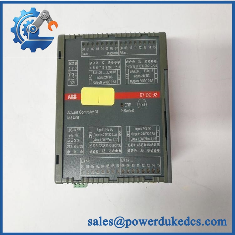
ABB 07DC92 GJR5252200R0101
ABB’s published product data identifies the part as a 07DC92 Digital In-/Output Module, 24, with 32 configurable digital I/Os, 24 V DC supply, CS31 communication, and 0.3 kg net weight.
Installation & Configuration Guide
Estimated replacement time: 30–45 minutes
Stage 1 — Pre-Installation: 10 minutes
⚠️ Safety first.
- Notify production of the planned shutdown.
- Put the controlled process into a safe state.
- Switch off the AC31 control-system power.
- Isolate UPS power where applicable.
- Wait for the discharge period specified by the system documentation.
- Wear an ESD wrist strap.
Prepare:
- PH1 screwdriver
- Multimeter
- ESD wrist strap and mat
- Cable labels
- Marker
- Phone/camera
- AC31 wiring diagram
- ABB 07DC92 documentation
Photograph the old module before removing it.
Record:
- Complete part number
- Serial number
- Module position
- Every cable connection
- CS31 bus wiring
- Terminal labels
- Any configuration switches
Stage 2 — Remove the Old Module: 5–10 minutes
- Confirm power is isolated.
- Label every wire.
- Photograph the terminal block.
- Disconnect the field wiring.
- Disconnect the bus connection.
- Release the DIN-rail fixing or mounting screws.
- Remove the module carefully.
Inspect the terminals and bus connection.
Look for:
- Loose conductors
- Corrosion
- Bent contacts
- Heat discoloration
- Damaged insulation
Do not pull directly on field wires.
Stage 3 — Install the Replacement: 10 minutes
- Verify 07DC92 / GJR5252200R0101.
- Compare the terminal arrangement with the old unit.
- Mount the module on the appropriate DIN rail or mounting points.
- Reconnect the bus.
- Restore field wiring according to the original labels and drawing.
- Check polarity.
- Check each terminal for mechanical tightness.
- Confirm that the module is firmly mounted.
The 07DC92 uses pluggable screw terminals and supports cable cross-sections from 0.08 to 1.5 mm².
Stage 4 — Power-On & Testing: 10–20 minutes
Before energizing:
- Check 24 V DC supply polarity.
- Verify the connection.
- Check field wiring.
- Confirm no loose strands are touching adjacent terminals.
- Remove tools from the cabinet.
Power the system according to the approved procedure.
Check:
- Module diagnostic indication.
- communication.
- Input status LEDs.
- Output status.
- Controller diagnostics.
- HMI/SCADA indications.
Test several input and output points.
Then test the complete control sequence.
Do not test an output by randomly shorting terminals. Use the approved load or simulation method.
Quality Inspection SOP
1. Incoming Inspection
Verify:
- ABB identification label
- 07DC92 designation
- GJR5252200R0101 ordering number
- Serial number
- Packaging condition
- Terminal condition
- DIN-rail mounting mechanism
- PCB condition
- Signs of corrosion or repair
For traceability, retain product photographs with the purchase record.
2. Live Test
Use a compatible ABB / test environment where available.
Check:
- 24 V DC power-up
- Diagnostic LEDs
- communication
- Digital inputs
- Digital outputs
- Output switching
- Fault indication
The module provides 32 yellow LEDs for signal indication, along with diagnostic indication and a test button according to published product information.
Generate a Test Report with:
- Part number
- Serial number
- Test date
- Test equipment
- Test results
- Technician
3. Electrical Testing
Check, as applicable:
- Supply voltage
- Polarity
- Ground continuity
- Insulation condition
- Output behavior
- Short-circuit protection response
Use the ABB documentation for test limits.
Do not apply an arbitrary hipot or insulation test voltage to an assembled module.
4. Configuration Verification
Confirm:
- station configuration
- I/O address allocation
- Controller configuration
- Input/output assignment
- Existing application program
The 07DC92 occupies digital input and output addressing on the bus, so the controller configuration should be backed up before replacement.
5. Final QC and Packaging
After testing:
- QC inspector signs the report
- Place the module in an ESD bag
- Add bubble protection
- Use a rigid carton
- Attach QC label
- Record inspection date and serial number
Test photos and videos can be supplied when available.
Spare Inventory Recommendation
This is a legacy component, so inventory policy should account for lifecycle risk.
| Situation | Suggested Stock Level |
|---|---|
| One critical cabinet | Min 1 / Max 1 |
| Several identical cabinets | Min 1 / Max 2 |
| High annual consumption | Min 1 / Max 3 |
| Low-use application | Min 0 / Max 1 |
| Long supplier lead time | Hold 1 tested spare |
| EOL concern | Review last-time-buy |
| Shared plant inventory | Centralize 1–2 tested units |
For a critical installation, one tested buffer module is usually more rational than buying a large quantity.
The 0.3 kg net weight also keeps physical carrying cost modest; the bigger concern is obsolescence and future availability.
Technical Replacement Risks
1. Addressing Error
The module communicates through the system bus.
A replacement that powers up can still fail at system level if the controller configuration or station addressing is wrong.
Take a backup before removal.
2. Input / Output Assignment
This module has 32 configurable digital channels.
That flexibility can also cause a commissioning mistake.
A channel configured as an input in the old application should not be treated as an output simply because the terminal physically accepts the connection.
3. Output Load
The published rating is 0.5 A nominal output current.
Check the actual field load before commissioning.
A relay coil, solenoid, contactor, or lamp circuit may have different inrush characteristics. Don’t judge the load only from its steady-state current.
4. Terminal Wiring Error
The module uses pluggable screw terminals.
Photograph the old terminal block.
Then reproduce the wiring one conductor at a time.
A reversed 24 V DC connection can waste more time than the actual module replacement.
5. ESD Damage
Use an ESD wrist strap and mat when handling the module.
Keep the replacement inside its ESD packaging until installation.
Do not touch exposed PCB contacts.
FAQ
1. What is ABB 07DC92 GJR5252200R0101?
It is a 32-channel configurable digital I/O module in the ABB family. The module operates as a remote bus device and uses 24 V DC supply.
2. How many I/O points does 07DC92 have?
It has 32 configurable digital I/Os.
Channels can be configured as inputs, outputs, or readable outputs. The I/O is divided into four electrically isolated groups.
3. What voltage does the ABB 07DC92 use?
The specified supply voltage is 24 V DC. The published data also lists 24 V DC output voltage.
Before replacement, measure the actual cabinet supply and verify it against the documentation.
4. Can this module directly replace another 07DC92?
If the existing unit is , it is the same ordering reference. Still, check the hardware label, wiring, configuration, and application program before commissioning.
Three checks are cheap:
- Match the part number.
- Match the terminal wiring.
- Verify the configuration.
5. Is ABB 07DC92 still a current product?
ABB’s published classification places the module under and previous series / I/Os and previous series, indicating that it belongs to a legacy product family.
For a plant that still depends on equipment, maintaining a controlled buffer stock is worth considering.
6. Is the output rating 0.5 A?
Yes. Published product data specifies a 0.5 A output current rating. The output stage uses transistors and has overload/short-circuit protection.
Still, check the actual load type and wiring before energizing field outputs.
7. What condition should I buy for a critical spare?
For a production-critical application, tested New Surplus or verified new stock is preferable.
Ask the supplier for:
- Actual product photos
- Complete label photo
- Serial number
- Test report
- Warranty
- Packing photos
- Actual lead time
The listed price should be treated as a reference price, not the final transaction price. For an old system, compare the purchase cost with downtime exposure and emergency procurement cost.











 Start Chat


