

Description
- Brand: ABB
- Full Model Number: SensyCal FCU400-IR
- Lifecycle Status: Legacy product; ABB documentation remains available
- Core Function in System: Contactless continuous temperature monitoring of live MV switchgear connections and circuit breakers
- Top 3 Hardcore Specs: Up to 12 pyrometers; 24 V DC ±5%; <1 second total system response
- Temperature Measurement: ±0.75% or ±0.75 °C of reading, whichever is larger
- Sensor Resolution: 10:1 optical resolution
- Standard Sensor Cable: 10 m
- Outputs: 3 digital alarm/error outputs; optional 4–20 mA and MODBUS
- Protection: IP40
- Condition & Lead Time: New OEM or tested legacy inventory; emergency dispatch subject to confirmed stock
ABB identifies the SensyCal FCU400-IR as a complete contactless temperature-monitoring system for contact points and circuit breakers in medium-voltage switchgear. One system can monitor up to 12 hot spots continuously.
Module 3: Technical Intro & Downtime Impact
A loose busbar connection, oxidized contact surface, or deteriorating circuit-breaker connection can develop abnormal contact resistance and generate localized heating while the switchgear remains energized. That makes early detection critical. The ABB SensyCal FCU400-IR uses infrared pyrometers to continuously monitor live contact points without requiring direct contact with energized conductors. ABB states that a single system can monitor up to 12 hot spots, helping maintenance personnel identify dangerous temperature increases before they develop into equipment damage or an unplanned switchgear outage.
The measurement computer operates from 24 V DC ±5% and has a documented total system response time of less than 1 second. Infrared sensor optical resolution is 10:1, standard sensor-to-computer cable length is 10 m, and measurement reproducibility is specified as ±0.75% or ±0.75 °C of the reading, whichever is greater. The system provides three digital outputs for pre-alarm, alarm, and device error, with optional analog and MODBUS outputs.
Module 4: Dynamic Emergency Swap & Configuration Guide
1. Pre-Swap Prep — Identify Every Infrared Measurement Channel
Place the switchgear monitoring system into the approved maintenance state before opening the secondary compartment. Record the FCU400-IR nameplate, sensor count, pyrometer locations, tag numbers, cable routing, alarm thresholds, and existing output configuration. The standard sensor cable is 10 m, while the system can support as many as 12 pyrometers.Use ESD protection, an insulated screwdriver set, a calibrated multimeter, and the site switchgear drawing.
2. Removal — Disconnect the Measurement Computer Without Disturbing Live-Part Sensors
The FCU400-IR measurement computer is installed in the secondary/control compartment, while its infrared pyrometers monitor the live primary-side measurement points without physical electrical contact. Follow the switchgear isolation procedure before servicing the equipment. Photograph and label every sensor connector, alarm output, optional analog/MODBUS interface, and supply connection. Disconnect the wiring at the measurement computer, release its enclosure mounting hardware, and remove the computer without pulling or bending the sensor cables.
3. Installation & Configuration — Restore the Exact Sensor and Tag Mapping
Mount the replacement FCU400-IR in the original cabinet position and reconnect the 24 V DC ±5% supply and every pyrometer to its original input. Sensor order matters: restore each pyrometer to the same physical measurement point and tag number used in the configuration. ABB documents configurable measurement points and hotspot identification through the local display. Do not assume that a visually identical pyrometer can be moved between channels without reviewing the system configuration.
4. Power-On Self-Test (POST) — Prove Temperature, Alarm, and Communications
Restore auxiliary power and verify normal startup of the measurement computer. Confirm that each connected pyrometer produces a valid temperature reading and that the displayed measurement corresponds to its actual physical hotspot. Check the programmed pre-alarm and main-alarm thresholds, then verify the associated digital outputs. Where fitted, validate the 4–20 mA maximum-temperature output and MODBUS communication. ABB specifies a system response time below one second, so the acceptance test should also verify that abnormal temperature changes reach the monitoring system without an unacceptable delay.
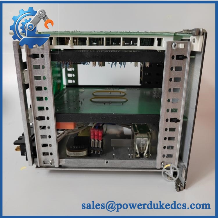
ABB SensyCal FCU400-IR
Module 5: Quality Assurance & Testing SOP
The should be tested as a complete infrared measurement system. Testing only the controller enclosure does not prove the sensor-to-measurement path.
- Identity verification: Record SensyCal nameplate data, serial number, hardware revision, supply specification, and installed option configuration.
- OEM anti-counterfeit visual inspection: Examine enclosure labels, PCB markings, terminal blocks, connectors, display assembly, and manufacturing identifiers against known ABB references.
- Mechanical inspection: Check the measurement computer enclosure, mounting hardware, cable entries, connectors, and sensor cables for impact damage, corrosion, cracked insulation, or loose terminations.
- Power-on self-test (POST): Apply 24 V DC ±5% and verify normal startup, local display operation, and absence of device-error indications.
- Infrared sensor inspection: Check every pyrometer for clean optical surfaces, secure mounting, intact cabling, and correct alignment with its designated measurement point.
- Temperature simulation: Use an approved controlled-temperature target or calibrated infrared test source to verify sensor response across representative operating points.
- 12-point channel verification: Where the installation uses the maximum configuration, individually test all 12 pyrometer channels and confirm correct channel-to-hotspot identification.
- Accuracy verification: Compare readings against calibrated reference temperatures and evaluate them against the documented ±0.75% or ±0.75 °C reproducibility specification.
- Alarm-output simulation: Drive individual measured values through the programmed pre-alarm and main-alarm limits and verify the associated digital outputs.
- Analog output verification: Where fitted, check the optional 4–20 mA output corresponding to the highest measured pyrometer temperature.
- MODBUS verification: Where installed, confirm RS485/RS232 communication, device addressing, data availability, and stable polling.
- Response-time verification: Confirm the complete measurement system responds within the documented <1 second system response requirement.
- Extended runtime test: Operate the complete sensor/measurement chain long enough to identify intermittent readings, sensor communication failures, false alarms, or abnormal temperature drift.
- Final QC record: Retain sensor-channel photographs, calibration results, alarm tests, communication logs, supply measurements, test date, technician sign-off, and final pass/fail status.
ABB specifically lists continuous live-part temperature monitoring, configurable warning/emergency thresholds, optional analog output, optional MODBUS, EMI/RFI shielding, and local indication of measurement points and maximum temperature values among the features.
Module 6: Maintenance & Reliability FAQ
1. Is ABB SensyCal a direct drop-in replacement, or does it require a firmware flash?
Do not assume a blind replacement. The is a configured measurement system, and the required sensor connection type and installed options affect the finished system. ABB’s documentation indicates that temperature-input configuration must be specified when ordering and cannot simply be changed on site. Verify the exact sensor count, sensor type, option cards, communication configuration, measurement-point assignments, and alarm parameters before installation.
2. Is it safe to replace the while the switchgear is running?
Do not assume that the measurement computer can be serviced live simply because the infrared sensors operate without direct contact with energized conductors. The measurement computer itself is connected to auxiliary power and external interfaces, while the sensors are positioned around energized MV equipment. Follow the switchgear manufacturer’s maintenance procedure and the site’s electrical isolation requirements before disconnecting wiring.
3. Will replacing cause my existing hotspot configuration to be lost?
The physical replacement does not inherently mean that the configured measurement points and alarm settings should be discarded. However, the existing configuration should be documented or backed up before replacement. Record every pyrometer’s channel, hotspot tag, alarm threshold, output assignment, communication setting, and ambient-temperature configuration. ABB’s operating documentation provides local configuration parameters including M-Bus address, baud rate, serial interface, and option settings.
4. How do I verify that an infrared sensor is measuring the correct hotspot?
First confirm physical alignment. Then compare the displayed value against a calibrated reference source or controlled thermal target. The documented 10:1 optical resolution means target size and sensor distance affect the measurement, so a sensor aimed incorrectly at surrounding metal can produce a plausible but misleading temperature value. (This is one of the most important field checks after replacing a sensor or disturbing its mounting.)
5. What are the warranty terms if the fails post-installation?
Warranty should follow the commercial terms for the exact unit and condition supplied. Retain the serial number, pre-shipment test report, sensor photographs, calibration results, configuration backup, installation date, and post-installation alarm records. For a temperature-monitoring system, those records help separate a failed measurement computer from pyrometer alignment, cable, configuration, or actual switchgear-temperature problems.











 Start Chat


