

Description
- Brand: ABB
- Full Model Number: UDA327AE02
- Lifecycle Status: Legacy / application-specific GMD hardware
- Core Function in System: Digital control interface for ABB Gearless Mill Drive control hardware
- Top 3 Hardcore Specs: UDA 327 digital card; B448 backplane installation; 833 µs Interrupt 0 control cycle
- System Association: ABB Gearless Mill Drive / cycloconverter control
- Control Role: Measurement and communication interface with bridge commutation hardware
- Physical Form: Plug-in backplane card
- Condition & Lead Time: New old stock or tested replacement; emergency dispatch subject to confirmed physical inventory
ABB’s published technical paper identifies the UDA 327 as a digital card mounted in backplane B448. The card provides measurement and communication with the bridge commutation card, and this activity is handled within the fastest control cluster at approximately 833 µs for a 50 Hz network.
Module 3: Technical Intro & Downtime Impact
A failed UDA327AE02 can interrupt the high-speed control path between the drive controller and bridge commutation hardware. In an ABB Gearless Mill Drive, that is a substantially different failure from losing a conventional supervisory I/O point: the affected control path participates in fast measurement and commutation-related functions. ABB’s published GMD documentation specifically places the UDA 327 digital card in B448 and states that it handles measurement and communication with the bridge commutation card.
The timing requirement is the critical engineering detail. ABB documents an Interrupt 0 cycle of 833 µs for a 50 Hz network, calculated as one twenty-fourth of the 20 ms voltage period. The same document describes the UDA 327 interface as part of the control logic associated with bridge commutation and protection-related functions. Because this is legacy GMD hardware, replacement should be based on the complete card identification, B448 position, software revision, and existing application configuration rather than visual similarity. (A card that powers up can still be incompatible with the installed control application.)
Module 4: Dynamic Emergency Swap & Configuration Guide
1. Pre-Swap Prep — Capture the Fast-Control Configuration
Place the GMD in the approved maintenance condition and verify that the power-conversion system is fully isolated according to the plant’s switching procedure. Photograph the UDA327AE02, its B448 rack position, adjacent cards, cable routing, and all visible revision markings. Back up the GMD controller configuration and record the installed software revision before removing the card. Use ESD protection, insulated tools, and the applicable ABB GMD wiring and rack drawings.
2. Removal — Withdraw the Plug-In Card Squarely
The UDA 327 is documented as a digital card installed in backplane B448. After confirming zero energy under the site’s electrical-safety procedure, disconnect any associated interface connections, release the card’s retaining hardware, and withdraw the board straight from the backplane. Do not twist the PCB while disengaging the connector; high-speed backplane contacts can be damaged by uneven extraction.
3. Installation & Configuration — Match Position and Application Revision
Install the replacement UDA327AE02 into the identical position and secure it mechanically. Reconnect the interfaces exactly as documented in the original configuration photographs and wiring drawings. Verify the card revision against the removed board and engineering records. Do not invent DIP-switch or address settings from generic UDA 327 listings; the actual GMD application configuration must determine the required hardware setup.
4. Power-On Self-Test (POST) — Prove Fast Commutation Feedback
Restore control power under the controlled commissioning procedure and confirm that the GMD controller completes its startup diagnostics without card or backplane faults. Verify that the UDA 327 is recognized by the control system and that the bridge-commutation communication path is available. Then perform the approved low-level and functional drive tests. ABB’s documentation identifies the UDA 327 as part of the measurement/communication path to the bridge commutation card, so acceptance should include actual control-path verification rather than a simple power indication.
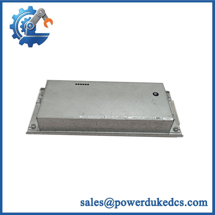
ABB UDA327AE02
Module 5: Quality Assurance & Testing SOP
The ABB UDA327AE02 should be treated as a high-speed legacy GMD control-interface card.
- Identity verification: Record UDA327AE02 identification, PCB markings, hardware revision, serial information, and associated position.
- OEM anti-counterfeit visual inspection: Examine ABB labels, PCB markings, connector construction, component placement, fasteners, and manufacturing identifiers.
- Mechanical inspection: Check PCB condition, edge contacts, backplane connector, retention hardware, contamination, corrosion, and evidence of thermal stress.
- Power-on self-test (POST): Install the card in an approved test environment and verify normal controller startup, card recognition, and diagnostic status.
- Backplane interface test: Verify reliable electrical engagement with the backplane and inspect for intermittent contact during controlled operation.
- Digital signal verification: Exercise the applicable digital communication and control interfaces using the approved GMD test fixture.
- Bridge communication test: Verify the measurement and communication path between UDA 327 and the bridge commutation interface.
- Timing verification: Where the laboratory setup permits, confirm behavior consistent with the documented fast control cycle. ABB’s GMD paper specifies 833 µs for Interrupt 0 on a 50 Hz network.
- Control-signal simulation: Apply representative simulated measurement and feedback signals and confirm correct response from the control application.
- Protection-path verification: Test the relevant diagnostic and protection interfaces without applying uncontrolled power-stage conditions.
- Extended runtime test: Operate the card under representative controller conditions long enough to expose intermittent backplane contact, communication loss, or thermal instability.
- Final QC record: Retain identification photographs, slot photographs, diagnostic results, communication-test records, timing observations, test date, technician sign-off, and final pass/fail status.
ABB’s GMD documentation also identifies the UDA 327 alongside other cards involved in bridge control, pulse amplification, and backplane supervision, reinforcing that the card should be tested as part of the complete drive-control architecture.
Module 6: Maintenance & Reliability FAQ
1. Is ABB a direct drop-in replacement, or does it require a firmware flash?
Do not assume a blind drop-in exchange. The UDA 327 is part of a GMD control architecture in which hardware and application software operate together. The card should match the installed position, hardware revision, and GMD software/configuration. A firmware transfer should only be performed when the documented ABB application procedure requires it.
2. Is it safe to hot-swap the while the GMD is running?
No. Treat this as non-hot-swappable unless the exact ABB system documentation provides a specific live-maintenance procedure. The UDA 327 interfaces with high-speed drive-control circuitry, and uncontrolled removal can interrupt commutation-related control functions. Fully isolate the applicable power and control circuits before extraction.
3. Will replacing the cause my current GMD program to be lost?
The UDA 327 is a digital control-interface card rather than the main application-storage device, so replacing the physical card should not by itself erase the GMD application. Still, back up the controller configuration, software revision, parameter database, and relevant drive settings before intervention. Restore or verify the configuration only after the replacement card has been accepted by the system.
4. What should I verify after installing ?
Verify card recognition, backplane health, communication with the bridge-control hardware, diagnostic status, measurement feedback, and the relevant GMD control functions. ABB documents the UDA 327 specifically as part of the measurement/communication path to the bridge commutation card, making that path the key acceptance test.
5. What are the warranty terms if the unit fails post-installation?
Warranty should follow the commercial terms for the supplied unit and its condition. Retain the serial number, pre-shipment test record, hardware-revision photographs, installation date, controller diagnostics, and post-installation test results. For legacy GMD hardware, those records are important when distinguishing a failed from a backplane fault, communication issue, configuration mismatch, or a problem in the bridge-control circuitry.











 Start Chat


