

Description
- Model & Brand: GE Multilin 369-C101
- Associated GE Part Number: 1753-0005
- Series: Multilin 369 Motor Management Relay
- Part Type: Lower Control Board / Replacement PCB
- Physical Dimensions: Exact board dimensions are not reliably published for the standalone 369-C101 PCB. The complete 369 relay uses a substantially larger panel-mounted enclosure, so do not use full-relay dimensions for board-level freight or cabinet planning.
- Estimated Shipping Weight: Approximately 0.3–0.6 kg for a protected PCB shipment; actual packed weight should control freight documentation.
- What’s in the Box: 369-C101 / 1753-0005 lower control board, ESD shielding protection, rigid PCB protection, and applicable inspection/QC documentation. The complete Multilin 369 relay enclosure, upper control board, power supply board, CTs, and field terminal hardware are not assumed.
Product Introduction
The GE 369-C101 is a lower control board used inside the Multilin 369 Motor Management Relay, rather than a complete relay. Industrial spare-parts records associate 369-C101 with GE part 1753-0005 and identify it specifically as the lower control board. That distinction should be preserved in purchasing and inventory records; ordering a complete 369 relay when only the lower PCB is required changes both cost and configuration risk.
Within the 369 architecture, the lower control electronics support the relay’s motor-protection, monitoring, control, and communication functions. The complete 369 platform provides three rear RS485 ports, a front RS232 service/programming port, Modbus RTU communications, programmable relays, metering, RTD options, and application-dependent communication options. Those functions belong to the complete relay system, however, and should not be represented as standalone specifications of the 369-C101 PCB.
Core Technical Specifications
| Parameter | Value |
|---|---|
| Manufacturer | GE General Electric / GE Multilin |
| Model | |
| GE Board Part Number | 1753-0005 |
| Product Family | Multilin 369 Motor Management Relay |
| Product Type | Lower Control Board |
| Installation | Internal PCB within Multilin 369 relay |
| Primary Function | Lower-level relay control electronics |
| Complete Relay Application | Three-phase motor protection, monitoring, and control |
| Processor | Board-level processor circuitry; exact device not reliably published for 369- |
| Main Memory | Exact standalone capacity not reliably published |
| Firmware | Resides in the complete relay’s control electronics; exact board-level revision must be verified from the unit |
| Communications on Complete 369 | 1 × RS232 front port + 3 × RS485 rear ports |
| Standard Protocol | Modbus RTU on complete 369 |
| Complete Relay Output Relays | 4 programmable output relays |
| Complete Relay RTD Capability | Up to 12 RTDs with R option |
| Complete Relay Metering | Voltage, current, power, PF, frequency and related quantities with applicable options |
| Control Power on Complete Relay | HI: 50–300 VDC / 60–265 VAC; LO: 20–60 VDC / 20–48 VAC |
| PCB Power Draw | Not reliably published for alone |
| PCB Heat Dissipation | Not reliably published for alone |
| Board Dimensions | Not reliably published for alone |
| Mounting | Internal 369 relay chassis |
| Hot Replacement | No — isolate the relay before board replacement |
| Lifecycle Position | Legacy / Discontinued |
Engineering identification note
GE’s 369 documentation defines the relay itself through an order code such as 369-HI-R-B-0-0-H-E, with the individual options determining RTD inputs, metering, backspin detection, fiber optics, communication protocols, harsh-environment construction, and enhanced diagnostics. The documentation also states that factory-installed option hardware is required for certain functions and that unauthorized field hardware modification can void the product warranty.
That matters when sourcing . The lower control board is only one part of a configured relay, so a replacement PCB should be matched against the original relay’s serial number, option set, firmware, and board revision rather than judged by the 369- identifier alone.
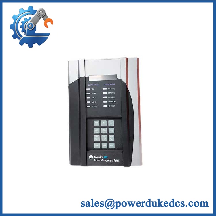
GE 369-C101
🚨 Global Compliance & Industry Certifications
The relevant compliance records are primarily associated with the complete Multilin 369 relay, not an independently certified bare lower control board.
- CE Mark: The 369 documentation identifies CE compliance under the applicable low-voltage and EMC directives/standards for the relay product.
- UL/cUL: GE’s 369 manual identifies cULus E83849 under UL/Canadian industrial-control requirements.
- Hazardous Location: The documentation identifies cULus E234799, Class I Division 2 for applicable configurations. This approval should be tied to the complete certified relay arrangement, not automatically to a replacement PCB.
- ATEX / IECEx: Do not assume standalone ATEX or IECEx certification for the 369- board unless the applicable certificate expressly covers that configuration.
- Marine / DNV GL: No standalone DNV GL approval should be assumed.
- ISO 9001: GE’s manual states manufacture under an ISO9001-registered quality program.
- Country of Origin: Establish from actual manufacturing traceability for the supplied board.
- HS Classification: Confirm the final customs classification with the importing country’s broker.
A Class I Division 2 approval matters because it establishes specific conditions for equipment installed where hazardous gases or vapors may be present. It does not mean any replacement PCB can automatically inherit that approval outside the documented relay configuration.
Verify specific lot certifications with OEM.
🚨 Long-Term Storage & Asset Preservation Guide
Keep the 369- in an ESD shielding bag with the PCB edge and connectors mechanically protected. Bare control boards should not be stacked directly on one another; pressure and electrostatic discharge can damage connectors and exposed circuitry.
GE’s 369 documentation specifically recommends storing the relay in a dry, corrosion-free environment away from direct sunlight. It also recommends powering the relay once per year for one continuous hour to reduce deterioration of electrolytic capacitors and the resulting failure risk. That preservation instruction applies to the relay platform and should be incorporated into the maintenance plan when the board is stored as part of a complete spare assembly.
For warehouse control, target below approximately 60% RH where practical and avoid condensation. Record the board revision, serial/traceability markings, and the firmware revision of the host 369 relay; the manual explicitly notes that firmware shown on the factory label may later have been changed in the field.
Physical Installation Prerequisites
The 369- is an internal relay PCB, not a DIN-rail or VME-mounted module. Replacement requires opening the Multilin 369 enclosure and following the approved service procedure.
Disconnect and isolate the relay before board removal. GE’s safety guidance explicitly requires hazardous live circuits and power sources to be isolated before visual inspection, testing, or maintenance.
Maintain a reliable protective-earth connection. GE specifies that equipment grounding must remain intact during operation and service, with short ground leads bonded to the facility grounding system; the manual also calls for an appropriately sized PE connection.
Preserve the exact cable, connector, and board-to-board arrangement before removing the . Do not force the PCB into the chassis, and do not change factory hardware options simply to make a replacement appear compatible. GE states that field hardware modification of the relay is not supported and can void the product warranty.
Because this is a legacy internal PCB, there is no defensible universal 50 mm clearance requirement for the board itself. Use the complete 369 enclosure installation dimensions and maintain the relay’s designed ventilation path; the manual states that no special ventilation is required when ambient conditions remain within specification.
Buyer’s FAQ — Logistics & Compliance Focus
Q: What HS Tariff Code should be used for GE 369-?
A: The is a replacement control PCB for an industrial motor-management relay. The final Harmonized System classification depends on the importing country’s tariff interpretation and whether customs treats the item as a replacement part or a functional control apparatus. Have the importer or customs broker confirm the final code.
Q: Can I use a GE 369 relay’s Country of Origin for the board?
A: Only when the documentation specifically covers the supplied board or the applicable manufacturing lot. COO should not be inferred from the current seller location or from the origin of the complete relay that originally contained the board.
Q: Does the 369- arrive with the latest firmware pre-loaded?
A: Do not assume it. The is an internal lower control board, while firmware belongs to the control electronics of the complete 369 relay. GE’s documentation provides a firmware history and notes that the firmware printed on the factory label may not match the current field-installed revision. Record the existing relay firmware before replacing the board and verify compatibility afterward.
Q: How should shipping insurance and physical packing be handled?
A: Insure the board for its documented commercial replacement value and retain photographs of the PCB identification, connector surfaces, and packaging before dispatch. Use an ESD shielding bag, rigid support around the board edges, moisture protection, and internal cushioning; do not allow the PCB to move freely inside the carton.











 Start Chat


