

Description
- Brand: GE Multilin
- Full Model Number: 369-HI-R-M-0-0-0-0
- System/Series Family: Multilin 369 Motor Management Relay
- Core Function: Three-phase motor protection, monitoring, metering, and control
- Top 3 Hardcore Specs: 110–250 VDC / 100–240 VAC control power; 1 A or 5 A phase-current inputs; 12 built-in RTD inputs
- Stock Status: New Surplus — exact firmware and hardware revision to be confirmed
The GE Multilin 369-HI-R-M-0-0-0-0 is a high-control-power motor management relay configured with the R RTD option and M metering option. GE’s 369 manual confirms that the R option provides 12 additional built-in RTD inputs, while the M option provides additional metering capability.
Module 3: Technical Product Introduction
Motor protection becomes considerably more useful when electrical loading and winding or bearing temperatures are evaluated together. The 369-HI-R-M-0-0-0-0 combines motor protection and monitoring with 12 built-in RTD inputs and the optional metering package. The HI control-power version accepts a broad auxiliary supply range; GE documentation identifies HI control power as the required ordering selection for high-voltage auxiliary applications.
The relay supports 1 A and 5 A phase-current secondary inputs, while its R option provides 12 RTD channels. The M option adds metering capability, and the relay supports waveform capture, event recording, and data logging. A published GE technical reference specifies 1.04 ms/sample True RMS phase-current conversion and waveform capture using three buffers containing 16 cycles of current and voltage channels.
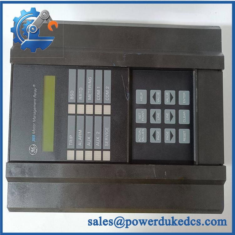
GE 369-HI-R-M-0-0-0-0
Module 4: Application Scenarios & Field Realities
- For medium-sized three-phase motors, the 369 combines thermal overload, current-unbalance, phase-reversal, undercurrent, overcurrent, and other protection functions in one relay. GE identifies the 369 specifically for motor protection and management applications.
- Where winding or bearing temperature is part of the protection scheme, the R option is significant. It provides 12 built-in RTD inputs, allowing temperature measurements to be incorporated into the motor protection strategy rather than handled only by separate instrumentation.
- During a motor-trip investigation, waveform capture and event records can help distinguish electrical disturbances from thermal or mechanical problems. Save the relay’s existing event data before replacing the unit whenever the relay remains operational.
- For pump and compressor applications, the relay can monitor starting behavior, loading, thermal condition, and abnormal current conditions. If the protected motor has a demanding starting cycle, preserve the original start-inhibit and overload settings during migration.
Module 5: Migration, Compatibility & Installation Traps
Replacement Matrix
| Replacement Type | 369-HI-R-M-0-0-0-0 Assessment | Engineering Requirement |
|---|---|---|
| Drop-in Replacement | Yes, for an exact configuration match | Match HI power, R RTD option, M metering option, hardware revision, and terminal configuration |
| Software Compatible | Configuration-dependent | Restore setpoints, motor data, protection curves, logic, and communication parameters |
| Hardware Modification Required | Potentially for another 369 variant | Required if RTD, metering, communications, power, or other option hardware differs |
Field Trap 1 — R does not mean a generic temperature input:
The R option specifically provides 12 additional built-in RTD inputs. GE documentation also specifies RTD sensing characteristics and supported sensor types. Verify the installed motor’s actual RTD wiring and sensor type before transferring the configuration.
Field Trap 2 — Preserve the complete option code:
GE states that the 369 order code is constructed from individual feature selections and that hardware-dependent options must be installed at the factory. Field hardware modifications can void the product warranty. Therefore, another 369 with a different option sequence should not automatically be considered equivalent.
Installation note: Isolate the motor and control-power circuits before replacement. CT secondary circuits require particular care; never open an energized CT secondary. Record all phase-current connections, RTD wiring, trip outputs, motor data, and existing setpoints before removing the relay.
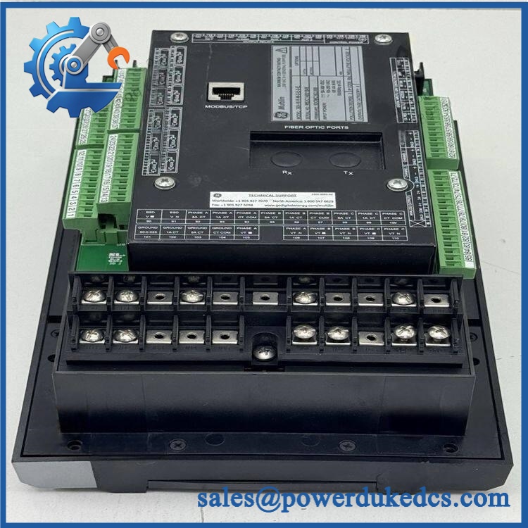
GE 369-HI-R-M-0-0-0-0
Module 6: Quality Assurance SOP
- OEM identification inspection — Verify GE Multilin 369-HI-R-M-0-0-0-0, serial number, manufacturing information, firmware revision, and hardware revision.
- Option-code inspection — Confirm the HI, R, and M selections against the physical relay and original documentation. GE’s manual identifies the R option as 12 built-in RTD inputs.
- Physical inspection — Examine the front panel, LCD, keypad, LEDs, terminal blocks, communication ports, enclosure, and accessible PCB areas for damage, corrosion, contamination, or previous repair.
- OEM anti-counterfeit visual inspection — Compare GE Multilin labeling, enclosure construction, terminal layout, PCB markings, connector arrangement, and manufacturing identifiers against authenticated reference hardware.
- Power-on self-test (POST) — Apply the correct HI control power in a controlled test environment and verify startup, display operation, LED status, diagnostic messages, and self-test results.
- Current-input verification — Use a calibrated relay test set to inject representative 1 A or 5 A phase-current signals and verify measurement scaling, phase relationships, frequency, and metering response.
- RTD verification — Test the 12 RTD channels with appropriate calibrated resistance simulators. Confirm channel identification, temperature conversion, alarm thresholds, and fault detection.
- Protection-function verification — Test applicable thermal overload, phase-current, current-unbalance, ground-fault, undercurrent, mechanical-jam, and start-related protection functions according to the customer’s approved settings.
- Communication handshake verification — Test the applicable RS-232/RS-485 communication interfaces and verify stable communication with the approved configuration. The relay can also use EnerVista 369 Setup for setpoint management and firmware updates.
- Event and waveform verification — Generate controlled test events and confirm correct event capture, timestamps, waveform recording, and relay status indications.
- Settings verification — Compare motor full-load current, CT ratio, acceleration time, thermal model, RTD assignments, protection thresholds, trip logic, and communications settings against the customer’s approved configuration.
- Final traceability record — Photograph the complete nameplate and option code, document firmware and hardware revisions, retain all test results, and package the relay using ESD-safe protective material.
For GE 369-HI-R-M-0-0-0-0, the decisive identification points are HI control power, R with 12 RTD inputs, and M metering. GE’s own manual confirms that the 369 is a configurable relay and that hardware-dependent options must be matched rather than assumed. Before commissioning a replacement, preserve the original relay’s motor settings, RTD assignments, CT configuration, protection curves, and communication parameters.











 Start Chat


