

Description
- Brand: GE Nexus Controls
- Full Model Number: 369B1843G5009
- System/Series Family: Nexus Controls OnCore Safety System
- One-Sentence Core Function: 24-channel safety digital-input module for acquisition of discrete field signals within the Nexus Controls I/O architecture
- Top 3 Hardcore Specs: 24 digital inputs; 20.4–28.8 VDC module supply; 5.0 W power consumption
- Stock Status: New Surplus / Fully Tested Refurbished — exact SDI60 identity and hardware condition verified before shipment
Module 3: Commercial-Technical Deep Dive
When a turbine safety-system input card fails, the problem is not limited to losing a few status points; the affected input path can alter permissives, trips, alarms, and sequence logic. GE 369B1843G5009 is the catalogue number for the SDI60, 24-channel digital input module in the Nexus Controls OnCore safety-system family. Baker Hughes documentation explicitly maps SDI60 (369B1843G5009) to a 24-channel digital input module, while the current Nexus Controls manual lists the SDI60 as a safety I/O module with a 20.4–28.8 VDC supply range and 5.0 W power consumption.
For procurement, channel count and system pairing are the hard identifiers. The SDI60 is not the same item as its associated BSDI60-F base board, 369B1843G5010; Baker Hughes lists those as separate catalog items. The public Nexus Controls manual confirms the module-level power requirement, while secondary references describe the SDI60 as a 24-channel digital-input device. Some reseller pages publish additional input-voltage, diagnostic, and installation claims that are not established by the manufacturer documentation reviewed here, so those values should not be used as guaranteed specifications without checking the applicable system manual and exact hardware revision.
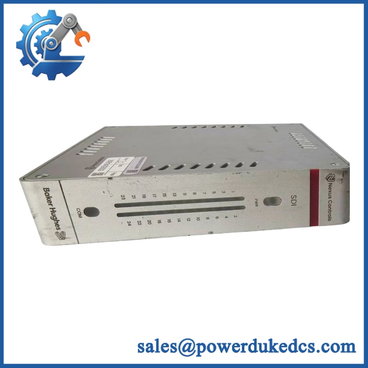
GE 369B1843G5009
Module 4: Compatibility & Installation Traps
Migration/Compatibility
- Replacement status: Configuration-specific digital-input replacement within the Nexus Controls OnCore safety-system architecture.
- Official identification: / 369B1843G5009, listed by Baker Hughes/Nexus Controls as a 24-channel digital input module.
- Base-board relationship: The corresponding BSDI60-F base board is 369B1843G5010. Do not confuse the electronics module with the physical base/interface assembly.
- Firmware requirement: No independent firmware update should be assumed for a like-for-like input-module replacement. Record the installed hardware revision and host-controller configuration before removal.
- Logic rewrite: Normally not required for a same-part-number replacement, but channel mapping, input polarity, filtering, diagnostics, and safety logic must be validated after installation.
- Supply requirement: The current Nexus Controls manual specifies 20.4–28.8 VDC and 5.0 W for .
⚠️ Field Traps (Watch Out)
- Module versus base board: Ordering 369B1843G5009 does not mean ordering 369B1843G5010. The first is the input module; the second is the BSDI60-F base board. Verify which assembly is actually defective.
- Input-channel mapping: A successful module power-up does not prove that all 24 channels are correctly assigned. Preserve the original channel map and verify each critical field point after replacement.
- Safety logic validation: Inputs associated with trips, permissives, shutdowns, and interlocks require point-by-point verification. Do not return a turbine or process train to automatic operation based only on a module status indication.
- Supply mismatch: The module’s specified supply is 20.4–28.8 VDC. Verify the actual backplane supply before energizing; do not substitute assumptions from unrelated Nexus I/O families.
- ESD handling: Use grounded ESD controls when handling the module and protect the backplane connector during storage and installation.
Module 5: Quality Assurance SOP
Our pre-shipment inspection for a GE 369B1843G5009 / focuses on exact identity, supply integrity, and all 24 digital-input paths:
- OEM anti-counterfeit visual inspection — verify GE/Nexus Controls identification, designation, complete 369B1843G5009 number, serial or revision markings, connector construction, PCB condition, and manufacturing labels.
- Part-number capture — photograph the front, rear, label area, and all secondary identification markings.
- Module/base separation check — confirm the supplied item is the electronics module and identify the installed or supplied BSDI60-F base board separately.
- PCB condition inspection — inspect connectors, solder joints, protection components, contamination, corrosion, and signs of thermal stress.
- Power-input verification — verify the test setup provides the documented 20.4–28.8 VDC supply range.
- Power-on self-test (POST) — energize the module in a compatible Nexus test environment and monitor startup behavior, status indications, abnormal current draw, and diagnostic response.
- 24-channel digital-input test — stimulate each available input individually with the approved test source and verify that the corresponding channel state is correctly detected.
- Threshold and transition testing — where the approved test procedure defines thresholds, verify both input activation and deactivation behavior rather than checking only one state.
- Channel-isolation verification — test representative channels for unintended cross-channel influence or unstable transitions.
- Controller handshake verification — connect the module to the compatible Nexus Controls host environment and confirm correct I/O recognition and data exchange.
- Safety-I/O application test — where the test environment permits, verify representative trip, permissive, alarm, and status points without connecting the module to live plant equipment.
- Extended observation — monitor all tested channels for intermittent changes, communication faults, or temperature rise during controlled operation.
- Configuration record — document part number, hardware revision, supply voltage, current/power observations, channel-test results, and photographs.
- Final QC review — cross-check the recorded module identity against the customer’s exact replacement requirement.
- ESD packaging — use antistatic protection, connector guards, mechanical cushioning, and moisture protection before shipment.
The manufacturer documentation establishes the key fixed points used for inspection: , 24 channels, 20.4–28.8 VDC, and 5.0 W. Baker Hughes separately identifies 369B1843G5010 as the base board, which should be recorded whenever the module is supplied as part of a complete assembly.
Module 6: CRO-Driven Buyer FAQ
1. Is GE 369B1843G5009 obsolete, and how do I verify an authentic replacement?
The part is associated with the Nexus Controls OnCore safety-system platform. Baker Hughes documentation explicitly identifies , 369B1843G5009 as the 24-channel digital-input module. Verify the complete part number, designation, hardware revision, connector arrangement, and physical condition before acceptance.
2. How many digital inputs does 369B1843G5009 provide?
The manufacturer documentation identifies the as a 24-channel digital input module.
3. What supply does the require?
The current Nexus Controls manual specifies 20.4–28.8 VDC with approximately 5.0 W power consumption for the .
4. Can 369B1843G5009 be hot-swapped?
Do not assume live replacement is permitted simply because some secondary listings claim online replacement. The authoritative material reviewed here identifies the module and electrical characteristics but does not establish a universal hot-swap procedure for every installed OnCore configuration. Follow the applicable Nexus Controls maintenance procedure, site isolation requirements, and safety-system change-control process before removal.
5. Is 369B1843G5009 the same as 369B1843G5010?
No. 369B1843G5009 is the 24-channel digital-input module, while 369B1843G5010 is the BSDI60-F base board module. They are separate catalog items and should be ordered according to the failed assembly component.
6. What warranty and technical support should I expect?
Warranty duration should be stated on the quotation for the exact physical unit supplied. Technical support should cover part-number verification, /base-board identification, channel testing, host-system compatibility checks, and documented pre-shipment test results. It should not substitute for safety-system validation, trip-logic authorization, or site commissioning by qualified personnel.











 Start Chat


