

Description
- Model & Brand: GE / Nexus Controls 369B1859G0021
- Model Designation: MCD51
- Series: Nexus OnCore
- Part Type: iLink I/O Bus & 24 VDC Power Extension Module
- Physical Dimensions: 127 × 120 × 23 mm (H × W × D)
- Estimated Shipping Weight: Approximately 150 g net; final freight weight depends on ESD protection and outer packaging.
- What’s in the Box: MCD51 module, protective ESD packaging, mounting hardware where supplied, and applicable QC documentation. iLink extension cables, iLink terminator, fuses, and 24 VDC power supplies are separate items unless expressly included.
Product Introduction
The GE 369B1859G0021 (MCD51) mounts on the Nexus OnCore cabinet mounting plate and forms the interface between the controller’s iLink bus, the distributed I/O network, and the cabinet’s redundant 24 VDC power system. It is not an I/O signal module. Instead, it extends both communication and power to downstream Nexus I/O modules (a distinction that should remain explicit in warehouse master data).
Its architecture provides two physically independent redundant iLink paths, R and S, together with redundant 24 VDC inputs and protected power distribution to connected I/O equipment. In remote-I/O installations, the module can support twisted-pair or fiber-based extensions through the appropriate converters and cables. That makes the MCD51 a network-and-power infrastructure component whose correct cable pairing and redundancy arrangement are as important as the module itself.
Core Technical Specifications
| Parameter | Value |
|---|---|
| Manufacturer | GE / Nexus Controls |
| Model | MCD51 |
| Part Number | 369B1859G0021 |
| Product Family | Nexus OnCore |
| Product Type | iLink I/O Bus & Power Extension Module |
| Primary Function | iLink bus extension and 24 VDC power distribution |
| Controller Interface | 2 × DB-9 female iLink inputs |
| iLink Bus Outputs | 4 × DB-9 male outputs |
| Redundant Network Paths | R and S |
| Remote I/O Interface | 1 × 8-pin terminal block |
| 24 VDC Inputs | 2 redundant inputs |
| Input Supply | 24 VDC ±10% |
| Maximum Input Current | 10 A per input |
| iLink Power Outputs | 4 × 24 VDC ±10% |
| Maximum iLink Output Current | 4 A per output |
| Auxiliary Power Outputs | 8 |
| Maximum Auxiliary Output Current | 1.5 A per output |
| Output Protection | Individual supply overload protection |
| Auxiliary Power Source A | 24V_IN_A |
| Auxiliary Power Source B | 24V_IN_B |
| Remote I/O Medium | Twisted pair or fiber optic with applicable conversion hardware |
| Typical TP Remote-I/O Distance | Less than 300 m |
| Typical FO Distance | Approximately 2–40 km, configuration dependent |
| Maximum I/O Modules in Series Chain | 12 |
| Physical Dimensions | 127 × 120 × 23 mm |
| Weight | 150 g |
| Operating Temperature | -20°C to +70°C |
| Storage Temperature | -40°C to +80°C |
| Operating Humidity | 5–95% RH, non-condensing |
| Configuration | No module configuration required |
| Firmware | No standalone user firmware |
| Mounting | Cabinet mounting plate |
| Hot Replacement | Follow the documented MCD51 replacement procedure |
| Lifecycle Position | Active / Controlled Stock |
Power distribution architecture
The accepts two independent 24 VDC supplies, each rated at up to 10 A. It then distributes protected 24 VDC to both iLink buses and auxiliary devices.
Four dedicated iLink power outputs are rated at up to 4 A each, while eight auxiliary outputs can provide up to 1.5 A each. The output assignments are physically separated between the A and B supply sides, which supports redundant cabinet power arrangements.
Do not treat every 24 VDC terminal as interchangeable. The R/S network paths and A/B power paths are deliberately separated.
Communication architecture
The module provides two controller-facing iLink connections and four downstream iLink outputs. For a dual-redundant controller installation, both R and S communication paths should be maintained.
For remote I/O, Nexus documentation allows either twisted-pair or fiber-optic media. Fiber distances can reach several kilometers with the proper RS-485-to-fiber conversion equipment, while ordinary twisted-pair remote connections are normally kept below approximately 300 m.
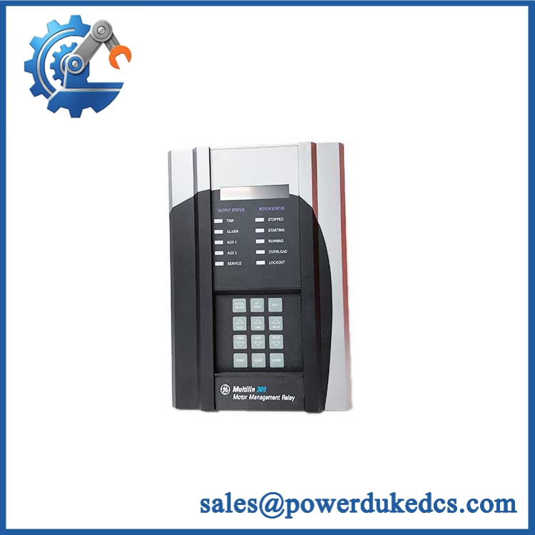
GE 369B1859G0021
🚨 Global Compliance & Industry Certifications
The is documented within the Nexus OnCore industrial control platform, with formal certification applying to defined equipment configurations rather than to an arbitrary loose module.
- CE Mark: Applicable Nexus OnCore documentation identifies EMC and European conformity requirements for the module family.
- UL/cUL: Verify the exact Nexus OnCore system certification and installation configuration for the supplied revision.
- ATEX: GE/Nexus documentation includes within the certified OnCore module family; the exact ordered suffix and installation conditions must match the applicable certificate.
- IECEx: appears in the applicable IECEx-certified Nexus OnCore module family. The certificate should be checked against the exact product suffix and installation conditions.
- UKCA: is included in the documented UK conformity-assessment module list.
- Marine / DNV GL: No standalone marine approval should be assumed without project-specific documentation.
- Country of Origin: Establish from the actual manufacturing/traceability record.
- HS Classification: Confirm the final tariff classification with the destination-country customs broker.
The hazardous-location certification matters because an ATEX/IECEx-certified configuration establishes the equipment conditions under which the module can be installed in a potentially explosive atmosphere. A standard unit should not automatically inherit that protection simply because the model family appears in a certificate.
Verify specific lot certifications with OEM.
🚨 Long-Term Storage & Asset Preservation Guide
Keep the inside an ESD shielding bag until installation. Protect all DB-9 connectors and terminal-block interfaces from dust, moisture, and mechanical impact; the low-profile 23 mm body makes connector damage easy to overlook during warehouse handling.
Store the module in a clean, dry environment without condensation. The documented operating humidity is 5–95% RH non-condensing, while a practical long-term warehouse target below approximately 60% RH provides a better corrosion-control margin.
Record the module’s complete / 369B1859G0021 identity and inspect the terminal blocks before issue. Unlike programmable Nexus I/O modules, the has no configuration information to load, so inventory quality depends heavily on correct physical identification and intact power/network interfaces.
For returned field units, inspect for discoloration near the power-input and distribution terminals. High-current 24 VDC connections can show thermal damage even when the module’s communication path remains operational.
Physical Installation Prerequisites
Mount the to the Nexus OnCore cabinet mounting plate using its four corner mounting points. The module is approximately 127 × 120 × 23 mm, so cable bend radius and connector access must be included in the actual cabinet layout.
Provide two redundant 24 VDC inputs, with each source rated for the required load and within ±10% of 24 VDC. The R and S iLink paths must be connected to their corresponding ports; do not cross-connect the redundant network paths during installation.
Eight auxiliary power outputs and four iLink power outputs are distributed across the module. Verify the intended A/B power assignment before wiring, particularly where downstream I/O is designed for redundant supply.
The does not use a normal VME backplane or DIN-rail I/O carrier. Its mechanical reference is the cabinet mounting plate, with field wiring and iLink cables connected directly to the module.
For remote I/O, verify cable type, termination, grounding, and the required RS-485/fiber conversion equipment before commissioning. The site procedure should also confirm whether one or two modules are required for the station’s selected redundancy architecture.
Buyer’s FAQ — Logistics & Compliance Focus
Q: What HS Tariff Code should be used for 369B1859G0021?
A: The is an industrial iLink bus and power-extension module. The final Harmonized System classification depends on the importing country’s tariff schedule and customs interpretation, so the importer or broker should confirm the code before the commercial invoice is issued.
Q: Does Country of Origin depend on where the is shipped from?
A: No. COO should be supported by the actual manufacturing or traceability documentation for 369B1859G0021. Warehouse location, seller address, and export port do not establish manufacturing origin.
Q: Does the contain the latest firmware pre-loaded?
A: No standalone firmware configuration is required. The Nexus OnCore hardware manual states that no configuration information is available for the . Its function is defined by the physical R/S iLink connections, redundant 24 VDC inputs, power-distribution wiring, and the connected Nexus architecture.
Q: Can I replace the without shutting down all 24 VDC power?
A: The Nexus OnCore maintenance procedure provides a specific MCD50/ replacement method, including removal of the module’s removable terminal blocks before the module itself is removed. Follow that procedure and the site’s LOTO requirements exactly; do not improvise a live-replacement method simply because the terminal blocks are removable.











 Start Chat


