

Description
- Brand: GE Multilin
- Full Model Number: 489-P5-HI-A20-T
- System/Series Family: Multilin 489 Generator Management Relay
- One-Sentence Core Function: Generator protection and management relay for monitoring electrical, thermal, and mechanical operating conditions
- Top 3 Hardcore Specs: 5 A phase CT inputs; 90–300 VDC / 70–265 VAC control power; 4 × 4–20 mA analog outputs
- Display: Enhanced display with larger LCD
- Ethernet: 10Base-T Ethernet
- Serial Communications: 1 × front RS-232; 2 × isolated RS-485 ports
- Protection Functions: Overcurrent, differential, loss of excitation, volts-per-hertz, under/overvoltage, frequency, thermal, breaker failure
- Analog Inputs: 4 configurable analog inputs
- Event Record: Up to 40 timestamped events
- Waveform Capture: 16-cycle trace for measured AC quantities
- Control Power: High-voltage input version
- Case: Drawout relay; case normally ordered separately
- Stock Status: New Surplus / Fully Tested Refurbished subject to availability
GE Multilin documentation identifies the 489 as a generator management relay with configurable protection, metering, communications, event recording, and waveform capture. The specific P5-HI-A20-T ordering code corresponds to 5 A phase CT secondaries, high control power, 4–20 mA analog outputs, enhanced display, and Ethernet.
Module 3: Commercial-Technical Deep Dive
A generator relay failure is rarely confined to one protection element. The GE 489-P5-HI-A20-T combines generator protection, metering, control, communications, and event analysis in a single drawout relay. The P5 configuration specifies 5 A phase CT secondaries, while HI identifies the high control-power range of 90–300 VDC or 70–265 VAC at 48–62 Hz. A20 provides four 4–20 mA analog outputs, and the T suffix adds 10Base-T Ethernet. The enhanced display option supplies the larger LCD used for local setup and interrogation.
For maintenance teams, the diagnostic depth is more valuable than the communications port count alone. The 489 supports three communication ports, including front RS-232 and two RS-485 interfaces, while its protection architecture covers functions such as stator thermal overload, phase and ground overcurrent, phase differential, loss of excitation, voltage protection, volts-per-hertz, breaker failure, and inadvertent energization. The relay stores up to 40 timestamped events, and each trip can generate a 16-cycle waveform trace for measured AC quantities. That historical data can reduce troubleshooting time after a protection operation—but only when the replacement carries the correct CT, power-supply, analog-output, display, and Ethernet configuration.
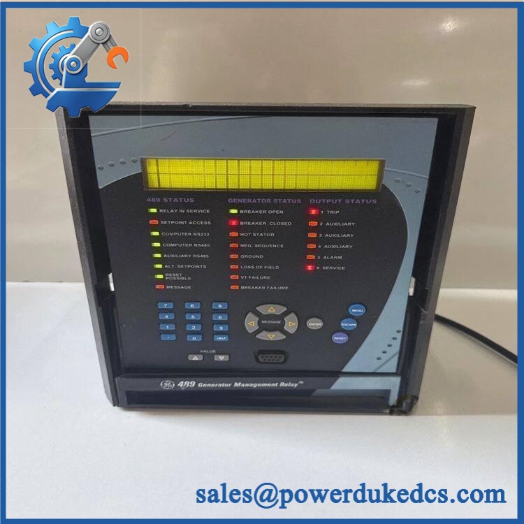
GE 489-P5-HI-A20-T
Module 4: Compatibility & Installation Traps
Migration/Compatibility
- Relay Family: GE Multilin 489 Generator Management Relay
- Ordering Code: 489-P5-HI-A20-T
- Phase CT Rating: 5 A secondary
- Control Power: 90–300 VDC or 70–265 VAC at 48–62 Hz
- Analog Outputs: 4 × 4–20 mA
- Display: Enhanced / larger LCD
- Ethernet: 10Base-T
- Communications: Front RS-232 plus two RS-485 ports
- Relay Format: Drawout unit
- Case Requirement: The 489 relay case is normally ordered separately.
- Replacement Type: Exact P5-HI-A20-T matching strongly preferred
- Configuration: Preserve protection settings, CT ratios, VT parameters, output assignments, communication settings, and programmable logic
- Logic Rewrite: Normally not required for an exact replacement, but all protection and control setpoints must be verified before energizing the generator
⚠️ Field Traps (Watch Out)
1. The 5 A CT designation is not optional.
The P5 code identifies the relay’s phase-current input configuration. GE explicitly warns that the 489’s nominal phase-current rating must match the connected CT secondary rating. A mismatch can compromise measurement accuracy and protection performance.
2. Do not omit the separate case requirement.
The 489 is a drawout relay unit; the drawout unit and relay case are separate procurement considerations. A replacement relay that arrives without the appropriate case does not restore a field installation by itself.
3. Verify the control-power range before energization.
The HI version accepts 90–300 VDC or 70–265 VAC at 48–62 Hz. Applying a low-voltage control supply intended for an LO version is not a configuration adjustment—it is the wrong hardware variant.
4. Preserve event and waveform data before replacement.
If the original relay is still readable, download setpoints, actual values, event records, and waveform captures before removal. Those records can be invaluable for determining whether the initiating fault is external to the relay.
Module 5: Quality Assurance SOP
Each available GE 489-P5-HI-A20-T should undergo a documented protection-relay inspection and functional test before shipment:
- OEM anti-counterfeit visual inspection: Verify GE Multilin markings, complete 489-P5-HI- ordering code, enhanced-display identification, Ethernet interface, serial ports, terminal layout, and manufacturing labels.
- Variant verification: Confirm P5 / HI / A20 / T configuration before testing.
- Drawout mechanism inspection: Check the relay housing interface, rear connectors, terminal condition, locking hardware, and mechanical alignment.
- PCB condition inspection: Inspect accessible electronics for corrosion, contamination, thermal damage, cracked components, and evidence of prior repair.
- Control-power precheck: Verify the test supply is within the HI relay’s 90–300 VDC or 70–265 VAC range before energization.
- Power-on self-test (POST): Energize the relay on an approved test bench and verify normal startup, LCD operation, keypad response, and diagnostic status.
- CT input verification: Inject calibrated 5 A-secondary-equivalent current signals and verify phase-current measurements.
- Voltage input verification: Apply controlled VT signals and confirm measured voltage and frequency values.
- Protection element test: Exercise representative phase overcurrent, ground overcurrent, under/overvoltage, frequency, thermal, and volts-per-hertz functions using a relay test set.
- Differential protection test: Where the test fixture supports it, simulate the required current conditions and verify pickup and trip behavior.
- Breaker control verification: Test assigned output relays against the documented control logic and verify expected contact operation.
- Analog-output verification: Drive representative measured values and confirm all four 4–20 mA outputs.
- RS-232 verification: Test the front service port using the approved setup software interface.
- RS-485 verification: Verify both rear serial communication ports independently.
- Ethernet handshake verification: Establish a controlled 10Base-T Ethernet connection and verify relay communication.
- Event recorder test: Generate a controlled test event and confirm timestamped event recording.
- Waveform capture test: Create a controlled trip condition and verify the expected waveform record is stored.
- Setpoint/configuration verification: Record CT ratio, VT ratio, protection pickups, delays, output assignments, communication settings, and firmware revision.
- Final QC record: Document the complete ordering code, measured electrical values, protection-test results, communications tests, firmware revision, and technician sign-off.
- ESD-safe packaging: Package the relay using ESD-protective material with rigid protection for the LCD, front keypad, rear connectors, and drawout mechanism.
GE’s manual provides dedicated hardware functional tests for output-current accuracy and phase-voltage/current measurement, so a meaningful outgoing test should include actual calibrated injection results rather than simply documenting that the LCD powers on.
Module 6: CRO-Driven Buyer FAQ
What is the GE 489-P5-HI-?
It is a GE Multilin 489 Generator Management Relay configured with 5 A phase CT inputs, high-range control power, four 4–20 mA analog outputs, enhanced display, and 10Base-T Ethernet.
What does P5-HI- mean?
P5 specifies 5 A phase CT secondaries. HI identifies the high control-power version. A20 provides four 4–20 mA analog outputs. T adds 10Base-T Ethernet. The enhanced display is also part of this configuration.
Can I replace a 489-P5-HI- with another 489 relay?
Only after matching the complete ordering code. A relay with a different CT input rating, control-power range, analog-output configuration, or display/network option is not automatically equivalent. GE’s ordering structure makes these options part of the hardware specification.
Does the replacement include the relay case?
The 489-P5-HI- is the drawout relay unit. The compatible 489 case is normally a separate item, so confirm whether the existing case is being reused or must be supplied with the replacement.
Can the 489 relay be removed while energized?
Do not assume live removal is permissible. The relay is connected to CT and VT circuits, control power, trip outputs, and potentially breaker-control wiring. Follow the site’s approved protection-relay isolation procedure, including proper CT secondary handling, before removing the drawout unit.
What warranty and technical support should I expect?
Warranty duration should be stated for the exact unit condition and test status on the quotation. Technical support should cover ordering-code verification, CT/VT compatibility, protection-setting review, communication checks, and documented relay-test results. Generator protection coordination, system studies, and commissioning should be treated separately unless explicitly included.











 Start Chat


