

Description
-
- Model: GE 531X303MCPARG1
- Brand: GE / General Electric
- Series: 531X Boards / GE DC-300 family
- Part Type: AC Power Supply Board
- Core Function: Converts incoming AC power into regulated control-power rails used by the associated GE drive electronics.
- Key Identification: GE identifies this board in legacy drive documentation as an AC power supply board; secondary records associate it with older DC-300 drive systems.
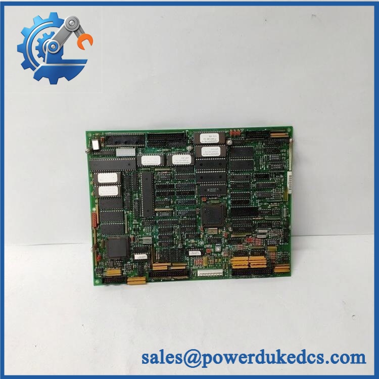
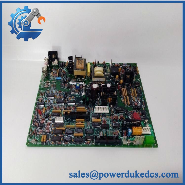
- Physical Construction: PCB assembly with transformers, heatsinks, fuses, relay, MOV protection, transistors, jumper switches, LEDs, and multiple board connectors.
Product Introduction
A DC-300 drive can exhibit apparently unrelated control faults when its internal control-power section begins to deteriorate. The GE 531X303MCPARG1 addresses that part of the architecture as the AC power-supply board, providing the internal power-conversion function required by the associated GE drive electronics. Public technical records specifically classify it as an AC Power Supply board and associate it with legacy GE general-purpose drives, including the DC-300.
Physically, this is a component-level industrial PCB rather than a complete drive or a conventional PLC power module. The board carries eight fuses, three transformers, six heatsinks, more than 20 transistors, a relay, MOV protection, two LEDs, and three jumper switches, according to the available board description. An alternate board number F31X303MCPAPG1 is also reported on the PCB.Because public sources disagree on some electrical values, the input and output ratings below distinguish documented information from supplier estimates.
Core Technical Specifications
Parameter Value Manufacturer GE / General Electric Catalog Number 531X303MCPARG1 Alternate Board Number F31X303MCPAPG1 reported on board Product Family GE 531X Boards Hardware Type AC Power Supply Board Associated Drive Family Legacy GE DC-300 and related drive systems Board Function AC-to-DC control power conversion Protection MOV surge protection; multiple fuses Fuses Eight populated fuse positions; includes 2 A and 5 A fuses Transformers 3 Heat Sinks 6 Transistors More than 20 Relay 1 Status Indicators 2 LEDs Jumper Switches 3 Board Connectors 2 vertical pin connectors, 7 headers, 6 stab-on connectors Terminal Strip 1 small terminal strip Reported Input Range 85–264 VAC in current secondary technical records Reported Output Multi-rail internal DC control power; exact rail values not reliably established from GE documentation located Reported Operating Temperature Approximately −20 to +55°C in one supplier record Reported Humidity 5–95%, non-condensing in secondary data Physical Dimensions Approx. 152 × 118 × 60 mm in one current supplier record Reported Weight Approximately 0.98 kg in one supplier record Lifecycle Legacy / obsolete The exact construction details come from a dedicated 531X303MCPARG1 parts record.
A caution is necessary around the electrical figures. Another current supplier page reports 85–264 VAC input, while other commercial listings give conflicting values such as 100–240 VAC input and 24 VDC/5 A output. I did not locate a GE primary document that establishes those values specifically for this exact board. They should therefore be treated as secondary reference data, not certified acceptance limits.
GE 531X303MCPARG1
Application Scenarios & Pain Points
Micro-case — legacy drive power fault: A DC-300 drive powers up intermittently, with downstream control boards repeatedly dropping out. After checking incoming mains and the external drive power path, instability in the internal AC power-supply board becomes a logical diagnostic branch.
For older manufacturing lines, the 531X303MCPARG1 can remain relevant where GE 531X/DC-300 drive hardware is still installed. Its role is particularly important because an internal power-board problem can create several secondary symptoms across otherwise functional control electronics.
In paper, metals, and process machinery, legacy DC-300 drives may control motors that cannot simply be taken offline for an unplanned modernization. A tested board spare allows maintenance teams to isolate the failed power section rather than immediately replacing the entire drive assembly.
At 50°C+ cabinet temperatures, inspect the board’s transformers, fuse area, semiconductor heatsinks, electrolytic capacitors, and surrounding wiring especially carefully. Thermal stress can make intermittent power faults much harder to reproduce on a cold bench.
With vs. without a verified spare: a known-good MCPARG1 can substantially reduce diagnostic time when the drive’s control electronics are otherwise intact; an untested surplus board can instead introduce another unknown into the troubleshooting process.
🚨 Common Error Codes & Diagnostic Symptoms
No authoritative GE document located establishes a universal numerical fault-code list specifically for 531X303MCPARG1. Troubleshooting should focus on the electrical symptoms and the associated drive diagnostics.
Symptom/Code: Drive control power missing or repeatedly collapses → Diagnosis: A failed input fuse, bridge/power device, transformer, regulator section, or PCB fault can interrupt the internal control-power supply → Action: Isolate the board, verify the incoming supply and protection chain, then replace the MCPARG1 when internal failure is confirmed.
Symptom/Code: Power-supply LED indication abnormal or absent → Diagnosis: The board’s documented LED indicators provide local status information; absence of the expected indication with correct input power can point toward an internal supply fault → Action: Check input voltage and fuse condition first, then substitute a verified board.
Symptom/Code: Repeated fuse opening after startup → Diagnosis: A downstream short, failed semiconductor, transformer fault, MOV failure, or overloaded control-power rail may be present; simply installing a larger fuse can create serious damage → Action: Do not bypass or increase fuse ratings; isolate the failed circuit and replace the board after the cause is established.
🚨 Cross-Reference & Lifecycle Migration
Cross-Reference
The strongest available identity mapping is:
GE 531X303MCPARG1 → AC Power Supply Board → 531X Boards / legacy DC-300 drive family
The board is also reported as carrying alternate board identification F31X303MCPAPG1.
Other 531X power-board numbers exist, including 531X303MCPALG1, 531X303MCPAYG1, and 531X303MCPBDG1. These should not be treated as drop-in substitutions merely because they share the 531X303MCPA/MCPB naming pattern. Their circuit architecture and intended drive platform may differ.
Firmware Requirement
The MCPARG1 is a power-supply board, not a programmable CPU. No user firmware flashing procedure is applicable to the board itself.
System-level compatibility instead depends on the correct drive model, board revision, connector arrangement, jumper configuration, fuse specification, and electrical characteristics.
Lifecycle Status
Lifecycle: Legacy / Obsolete.
The associated GE 531X/DC-300 drive technology is an older product generation. Specialist industrial-parts records describe the 531X303MCPARG1 as obsolete/legacy hardware, while repair listings also identify the board as discontinued.;
For buffer-stock planning, this part should be managed as a critical legacy spare where the associated drive remains operationally important. Preserve at least one electrically tested unit for high-consequence drives and record the exact board revision.
Field Engineer’s Tech Notes
First warning: do not treat a blown fuse as the root cause. The board contains multiple fuses, including reported 2 A and 5 A devices. A replacement fuse that opens immediately is telling you something; repeatedly fitting new fuses without locating the downstream failure can damage transformers, semiconductor devices, or PCB traces.
Second warning: document every jumper position before removal. The board has three jumper switches, and their settings can be part of the hardware configuration. Photograph the complete board from both sides before disconnecting anything (especially when working on equipment with undocumented field modifications).
The three transformers and multiple heatsinks also create several points where heat discoloration can reveal long-term stress. Inspect rather than assuming the PCB has failed digitally.
Strict QA & Testing SOP
1. Inbound identity verification
Confirm 531X303MCPARG1 and record the reported alternate identification F31X303MCPAPG1 where present. Photograph the full board, labels, jumper locations, fuse positions, transformers, and connectors.2. Mechanical inspection
Check the PCB for warped areas, cracked solder joints, damaged terminal strips, broken connector bodies, corrosion, contamination, and damaged mounting hardware.3. Component inspection
Examine the fuses, MOV, transformers, relay, heatsinks, transistors, capacitors, and resistor networks for burning, discoloration, cracking, or leakage.4. Jumper and connector verification
Record all three jumper settings and compare the connector arrangement with the customer’s removed board. Confirm that the six stab-on connectors and header locations correspond exactly.5. Electrical pre-check
Before energizing, inspect for shorts across relevant supply rails and check fuses against the documented board arrangement. Do not apply an arbitrary input voltage based only on a reseller listing.6. Controlled power-up
Use an isolated, current-limited test source appropriate to the confirmed board specification. Monitor input current, fuse behavior, transformer temperature, output rails, and LED status.7. Output verification
Measure the internal control-power outputs against the applicable GE drive service documentation. Because available secondary sources conflict on exact output values, acceptance limits should come from the specific DC-300/531X system documentation being serviced.8. Thermal observation
Operate the board under representative load while monitoring the transformer and heatsink temperatures. Investigate abnormal heating before releasing the board.9. Final preservation
After passing inspection, place the PCB in ESD shielding packaging, protect all edge and stab-on connectors, add impact cushioning, and retain the test record with the asset.Test videos are available when live-rig testing is performed and visual evidence is required by procurement.
Buyer’s FAQ
Is 531X303MCPARG1 the same as a complete GE DC-300 power supply?
No. It is identified as an AC power supply board within the drive architecture. It is a PCB-level component, not the complete DC-300 drive or a standalone cabinet power supply.
Can I substitute another 531X303MCPA board?
Not without engineering verification. Similar numbering does not establish electrical interchangeability. Confirm the board number, alternate number, jumper configuration, connector arrangement, fuse ratings, and host drive model before substitution.
Can the MCPARG1 be hot-swapped?
Do not assume so. This board handles AC-derived power and contains exposed high-energy circuitry, transformers, fuses, and semiconductors. The drive should be isolated from all hazardous electrical sources and properly discharged before board removal, following the applicable GE service procedure and plant lockout/tagout requirements.
How do I verify New Original authenticity and warranty?
Request photographs of the actual board showing 531X303MCPARG1, all revision markings, connector arrangement, jumper positions, and original packaging. For an obsolete power PCB, the supplier should state whether the unit is New Original, New Surplus, refurbished, or repaired, together with the test scope and warranty period.
For long-term asset control, record GE 531X303MCPARG1 + alternate board marking + hardware revision + fuse configuration + jumper settings + COO + QC result + packaging condition as the controlled spare identity.











 Start Chat


