

Description
- Model: 531X304IBDARG1
- Brand: General Electric (GE)
- Series: GE 531X / AC2000 drive-control hardware
- Part Type: Base Drive Control Card / Base Driver Board
- Core Function: Provides the base drive-control circuitry used to interface control signals with the power-stage circuitry in compatible GE drive systems.
- Key Specs: Legacy 531X PCB format; three crystal oscillator sections; multiple control/interface connectors; jumper-configurable circuits; transistor, resistor, capacitor, and diode networks; eight mechanical mounting points. GE parts references identify the board within AC2000 / Drive Control hardware.
Product Introduction
A drive cabinet can show healthy incoming power and still fail to produce the expected motor-control response when the base-drive circuitry has degraded. GE 531X304IBDARG1 is identified as a Base Drive Card / PC Base Drive Card for GE 531X drive hardware, with parts references placing it in the AC2000 drive-control family.
This is a legacy board built around discrete control hardware rather than a modern networked drive module. Inspection records for the exact part describe three crystal oscillators, six metal brackets, multiple jumper positions, five board-to-system connectors, and eight mounting points. Those details are useful when matching an old field spare because a visually similar 531X board may belong to another functional position (the board suffix must be checked before installation).
Core Technical Specifications
| Parameter | Value |
|---|---|
| Manufacturer | General Electric (GE) |
| Part Number | 531X304IBDARG1 |
| Functional Designation | IBDAR |
| Product Type | Base Drive Card / Base Driver Card |
| Product Family | GE 531X Boards |
| Associated Platform | AC2000 drive-control equipment |
| Primary Function | Base drive-control and interface circuitry |
| Oscillator Sections | 3 crystal oscillator sections reported |
| Board Connectors | 5 male/interface ports reported |
| Jumper Hardware | Multiple jumper-selectable circuit positions |
| Semiconductor Content | Transistors, integrated circuits, diodes |
| Passive Components | Resistors, resistor networks, capacitors |
| Mechanical Mounting | 8 mounting points reported |
| Heat-Sinking Hardware | Multiple metal bracket / heat-transfer structures reported |
| Processor | No independent microprocessor specification verified |
| Memory | No independently documented application-memory specification |
| Firmware | No standalone field firmware specification verified |
| Ethernet | No independent Ethernet interface documented for this board |
| Fieldbus | No independent fieldbus interface documented for this board |
| External Power Input | Supplied through the associated drive/control architecture; exact board-level input not verified |
| Operating Temperature | Exact OEM board-level rating not verified |
| Storage Temperature | Exact OEM board-level rating not verified |
| Dimensions | Exact GE mechanical drawing not verified |
| Net Weight | Exact GE net weight not verified |
| Lifecycle | Legacy / Obsolete service hardware |
Current industrial references consistently identify 531X304IBDARG1 as a base-drive card, while an equipment catalog places it under GE Drive Control / AC2000 inventory.
One secondary engineering reference describes the board architecture in more detail, including three repeated circuit sections, crystal oscillators, transformers, vertical pin headers, transistors, resistors, capacitors, and diodes. That information is useful for inspection, but it should not be treated as a substitute for a GE schematic.
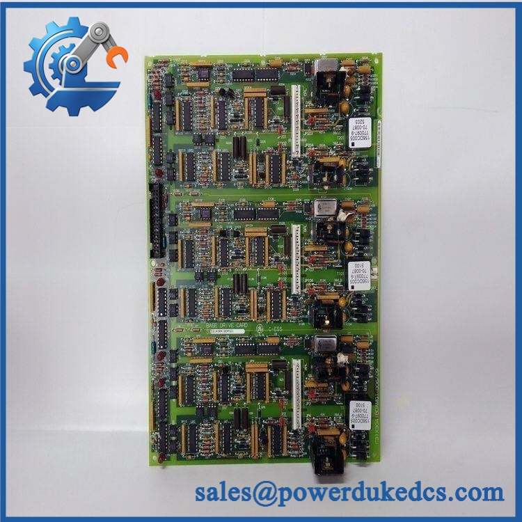
GE 531X304IBDARG1
Application Scenarios & Pain Points
Micro-case — a drive stops responding after a control-board fault. When the control command is present but the power stage does not receive the expected drive signal, technicians often start by checking the firing or interface path. A faulty base-drive board is one possible cause after the external control and power circuits have been verified.
In AC2000 drive cabinets, this board occupies the base-drive function within the larger control architecture. The historical GE inventory catalog explicitly places 531X304IBDARG1 under Drive Control and lists related 531X304 boards for the same equipment family.
During legacy migration, the board should be matched by complete part number and revision. Current service-parts records list 531X304IBDASG1 as a later base-drive card and one supplier’s obsolete-parts table states that 531X304IBDARG1 should use 531X304IBDASG1. That is useful migration evidence, but it does not by itself establish unrestricted drop-in compatibility for every cabinet.
In cabinets operating around 50°C, inspect the board’s heat-transfer hardware, nearby ventilation path, and connector condition carefully. The public references reviewed do not establish an exact OEM temperature rating for the individual IBDARG1 board, so cabinet measurements should control acceptance.
🚨 Common Error Codes & Diagnostic Symptoms
No reliable standalone numerical fault-code table was identified for 531X304IBDARG1. This board is normally diagnosed through the associated GE drive’s control behavior, feedback signals, status indications, and measurements.
Symptom/Code: Drive command present but base-drive output is missing or abnormal → Diagnosis: Possible failure in the board’s signal-conditioning, timing, oscillator, transistor, or interface circuitry; external inhibit and power-stage faults must be ruled out first. → Action: Verify upstream control signals and board supply conditions, then replace the board when the fault is localized.
Symptom/Code: Unstable drive firing/control behavior → Diagnosis: Possible timing-related hardware degradation, poor connector contact, damaged oscillator circuitry, or component failure. → Action: Inspect connectors and timing sections, then perform controlled board-level testing before replacing the unit.
Symptom/Code: Intermittent drive operation after thermal cycling → Diagnosis: Possible marginal solder joints, connector movement, component thermal drift, or degraded board interconnects. → Action: Inspect the PCB and interface hardware and verify the fault under controlled thermal conditions; replace the board if the fault follows the assembly.
🚨 Cross-Reference & Lifecycle Migration
Cross-Reference
The most important documented relationship is:
531X304IBDARG1 → 531X304IBDASG1
A current legacy-parts reference explicitly lists 531X304IBDARG1/EX — USE 531X304IBDASG1/EX, while another inventory record lists 531X304IBDARG1 alongside later 531X304IBDASG1 base-drive hardware.
A separate source also lists F31X304IBDAMG1 as a base-driver card and states that it carries 531X304IBDARG1 as a secondary identification number. This is useful when searching old GE/F31X documentation, but it should not be interpreted as proof that every F31X/531X identifier is interchangeable.
Firmware Requirement
No conventional firmware flashing procedure has been verified for the IBDARG1 board itself.
The available technical references describe a hardware-based base-drive circuit containing oscillators, transformers, discrete semiconductors, jumpers, and passive components rather than a modern software-configured controller.
Lifecycle Status
Status: Obsolete / Legacy
Current service-parts references show 531X304IBDARG1 as a legacy item and identify 531X304IBDASG1 as the hardware to use in one later replacement listing.
For buffer stock, retain the exact IBDARG1 identification and physical revision. Where the plant has multiple cabinets, record the cabinet application alongside the part number because visually similar 531X boards can perform completely different functions.
Field Engineer’s Tech Notes
Warning 1 — Do not adjust jumpers just because they look configurable.
The IBDARG1 has multiple jumper positions, and those settings can affect circuit behavior. Photograph every jumper before removal and compare the replacement against the approved cabinet drawing or known-good board. Never assume all positions should match a generic factory arrangement.
Warning 2 — Check the oscillator and connector sections before condemning the entire PCB.
The exact board is reported to contain three crystal oscillators and five interface ports. A loose connector or damaged timing component can create control symptoms that resemble a larger drive-system failure. Inspect these areas carefully before escalating the diagnosis.
Strict QA & Testing SOP
Step 1 — Part identity check
Confirm 531X304IBDARG1 from the physical board marking. Record every secondary identifier, revision, assembly number, and date/lot code.
Step 2 — PCB visual inspection
Inspect the complete board for corrosion, contamination, burned components, cracked solder joints, mechanical damage, and evidence of previous rework.
Step 3 — Connector inspection
Check all five reported interface connectors for bent contacts, oxidation, cracked housings, and abnormal solder-joint movement.
Step 4 — Jumper-state recording
Photograph and document every jumper position before any energized testing. Compare the configuration against the target drive application.
Step 5 — Oscillator inspection
Inspect the three crystal oscillator sections for physical damage and verify the associated circuitry using the approved schematic-level test method. Do not inject arbitrary signals into an undocumented node.
Step 6 — Passive-component inspection
Check capacitors, resistors, resistor networks, diodes, and transistors for visible thermal damage or measurable abnormality. Compare electrical measurements against the applicable GE service documentation.
Step 7 — Controlled power testing
Use a compatible /531X test environment. Do not apply an external supply directly to the PCB using guessed voltage values; the exact board supply arrangement depends on the associated drive architecture.
Step 8 — Timing and interface verification
Verify the timing/interface behavior of the board under controlled conditions and confirm stable communication with the associated drive-control hardware.
Step 9 — Extended observation
Run the assembly through repeated operating cycles and monitor for intermittent behavior, thermal drift, abnormal signals, or loss of control response.
Step 10 — Documentation
Record the board identity, jumper positions, test measurements, photographs, test equipment, and inspection result.
Step 11 — ESD-safe packaging
After testing, place the board in ESD shielding packaging and protect the connectors, oscillator components, and PCB mounting points against impact.
Test videos are available for applicable units tested on a compatible drive-control platform.
Buyer’s FAQ
Can I hot-swap the 531X304IBDARG1?
Do not assume hot-swapping is permitted. This is a drive-control PCB connected to the larger power-electronics system. Follow the approved maintenance procedure, isolate the drive, and verify the absence of hazardous energy before removing the board.
How do I verify a New Original 531X304IBDARG1?
Request photographs of the actual PCB, including the GE part number, secondary markings, jumper configuration, connectors, oscillator sections, and overall board condition. A generic photograph of a 531X304 board is not enough to establish the exact revision.
Is 531X304IBDASG1 the replacement for IBDARG1?
A legacy GE parts reference explicitly states 531X304IBDARG1/EX — USE 531X304IBDASG1/EX, and other inventory records identify IBDASG1 as a later base-drive card. Treat this as a migration reference and verify the cabinet-specific electrical and mechanical configuration before installation.
What warranty should I expect?
Warranty depends on the supplier’s written terms and the condition category of the board. For obsolete hardware, obtain the warranty period, functional-test scope, actual-board photographs, revision details, and return conditions before purchase. A supplier warranty should not be described as a GE factory warranty unless separately documented.











 Start Chat


