

Description
- Model: GE 531X304IBDASG1
- Brand: GE / General Electric
- Series: 531X Boards / AC2000
- Part Type: Base Drive Card / Base Driver Circuit Board
- Core Function: Provides the base-drive interface between the AC2000 drive control circuitry and its power-switching section.
- Key Identification: GE parts references identify 531X304IBDASG1 as an AC2000 Base Drive Card. The board is also associated in secondary records with F31X304IBDAMG1-006, which can assist physical identification but should not be treated as automatic interchangeability.
- Construction: The documented board contains three similar functional sections, each built around a transformer, vertical pin-header connector, two heatsinks, jumper switches, transistors, resistors, capacitors, and diodes.
Product Introduction
A legacy AC2000 drive can remain operational for decades, yet a degraded base-drive circuit can eventually prevent correct power-stage switching. The GE 531X304IBDASG1 is identified as an AC2000 Base Drive Card, placing it in the drive’s power-control interface rather than in the PLC or supervisory-control layer.
For replacement work, the physical board deserves close attention. Available documentation describes three repeated circuit sections with transformers, heatsinks, discrete switching devices, and configurable jumper switches. An alternate F31X304IBDAMG1-006 marking is also reported for this board family. (Keep photographs of the original board before removal; undocumented jumper positions can matter during legacy drive restoration.)
Core Technical Specifications
| Parameter | Value |
|---|---|
| Manufacturer | GE / General Electric |
| Catalog Number | 531X304IBDASG1 |
| Product Family | 531X Boards |
| Associated System | AC2000 Drive |
| Hardware Type | Base Drive Card / Base Driver Board |
| Primary Function | Drive power-stage interface and base-driver circuitry |
| Board Architecture | Three repeated functional sections |
| Transformers | 3 |
| Vertical Pin Headers | 3 |
| Heatsinks | 6 |
| Jumper Switches | Present |
| Transistors | Multiple discrete devices |
| Resistors / Networks | Multiple |
| Capacitors | Multiple |
| Diodes | Multiple |
| Board Mounting | PCB assembly with corner mounting holes |
| Internal Cutouts / Slots | Present |
| Reported Board Markings | Examples include 006/09 and C-ESS |
| Reported Alternate Identification | F31X304IBDAMG1-006 |
| Input Voltage | Not reliably verified for the exact board |
| Output Ratings | Not reliably verified for the exact board |
| Power Consumption | Not reliably verified |
| Heat Dissipation | Not reliably verified |
| Operating Temperature | Exact OEM specification not verified |
| Weight | Exact OEM value not verified |
| Dimensions | Exact OEM drawing not verified |
| Firmware | No standalone user-firmware specification established |
| Lifecycle | Legacy / obsolete |
The exact-part records consistently classify 531X304IBDASG1 as an Base Drive Card and provide the strongest available evidence regarding its internal physical construction.
Some secondary listings publish electrical values for this part, but the figures are inconsistent and are not adequately supported by a primary GE document for the exact IBDASG1 assembly. Those values should not be used as formal engineering acceptance criteria.
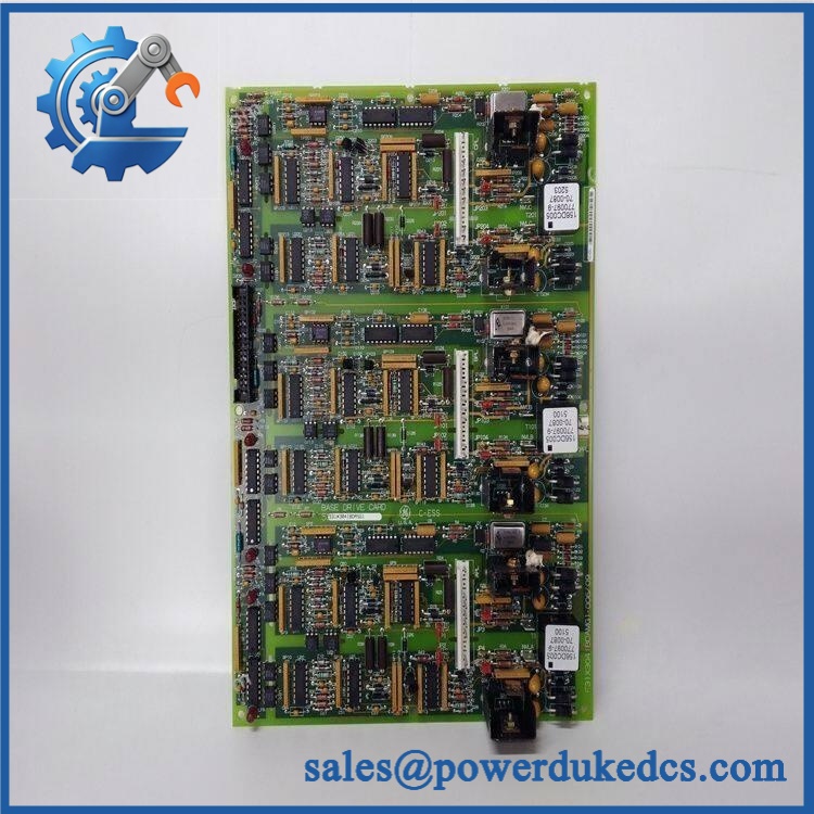
GE 531X304IBDASG1
Application Scenarios & Pain Points
Micro-case — failed drive startup: An drive receives its expected incoming power, but the motor does not respond correctly to a valid command. After external supply, control signals, and the power bridge have been checked, the base-drive card becomes a logical diagnostic target.
For older production machinery, the base-drive section is critical because it sits between low-level drive control electronics and higher-energy switching hardware. A fault can therefore appear as a broader drive malfunction even when other control boards remain operational.
In heavy industrial motor applications, an exact PCB spare can be useful when the existing drive cabinet, motor wiring, feedback arrangement, and control interface are still serviceable. Replacing one proven board may preserve the established installation rather than introducing a completely different drive architecture.
At 50°C+ cabinet temperatures, inspect the transformers, heatsinks, semiconductors, capacitors, and solder joints carefully. Thermal aging is especially relevant on a board containing multiple power-related components.
With versus without a verified spare: a tested 531X304IBDASG1 can reduce the fault-isolation path; an unverified surplus board introduces uncertainty around jumper positions, board revision, and component condition.
🚨 Common Error Codes & Diagnostic Symptoms
No authoritative GE source located establishes a universal numerical fault-code list specifically for 531X304IBDASG1. The following are therefore hardware symptoms rather than official GE error codes.
Symptom/Code: Drive fails to establish normal base-drive operation → Diagnosis: Possible fault in one or more driver sections, transformer circuits, switching devices, connector paths, or associated control circuitry → Action: Verify upstream controls and power-stage conditions, then replace the base-drive card when the fault follows the PCB.
Symptom/Code: Repeated drive trip immediately after startup → Diagnosis: A defective base-driver section may prevent correct gating or drive-interface operation, although the power bridge, feedback, and external control circuitry must be checked first → Action: Isolate the source of the trip and replace the board if the failure is demonstrated at PCB level.
Symptom/Code: One board section shows abnormal behavior or temperature → Diagnosis: The three repeated circuit sections provide a useful comparison point; a localized transformer, transistor, diode, resistor-network, or jumper fault may be present → Action: Compare the affected section against a known-good board and replace the PCB when internal failure is confirmed.
🚨 Cross-Reference & Lifecycle Migration
Exact Cross-Reference
GE 531X304IBDASG1 → Base Drive Card
This identification is supported by multiple industrial parts records.
A related board identification, F31X304IBDAMG1-006, is reported in secondary parts records. This is useful when checking the physical PCB label, but it should not be interpreted as a blanket replacement rule.
Other 531X304 drive boards exist, including 531X304IBDARG1, 531X304IBDAMG1, and 531X304IBDAFG1. Similar naming does not establish electrical equivalence. A current parts listing specifically shows 531X304IBDARG1 → use 531X304IBDASG1 in its legacy replacement notation, which is useful lifecycle evidence but still warrants confirmation against the actual drive configuration.
Firmware Requirement
The 531X304IBDASG1 is a hardware base-drive PCB, not a programmable PLC CPU. No standalone firmware-flashing procedure has been reliably established for this specific board.
Compatibility is driven instead by the host drive, board revision, connector arrangement, jumper configuration, and associated drive-control electronics.
Lifecycle Status
Lifecycle: Legacy / Obsolete.
The board belongs to the older GE 531X/ drive technology and is now primarily encountered through specialist industrial-spares, repair, and surplus channels. Current secondary catalogs continue to list the exact board, while related 531X304 variants are documented as replacement or repair items.
For buffer-stock planning, treat this as controlled legacy inventory. For a shutdown-critical drive, retain a tested spare and preserve the original board’s revision and jumper configuration.
Field Engineer’s Tech Notes
First warning: record every jumper position before removing the board. The documented construction specifically includes jumper switches, and an incorrect setting can produce abnormal drive behavior even when the replacement PCB itself is electrically healthy.
Second warning: inspect the transformer and heatsink areas for thermal damage. This board contains three transformers and six heatsinks, so heat discoloration, cracked solder joints, and stressed components can provide useful evidence of a long-term fault. Compare the three repeated sections rather than inspecting one area in isolation.
Use ESD protection throughout handling. Do not touch exposed connector contacts unnecessarily.
Strict QA & Testing SOP
1. Inbound identification
Verify 531X304IBDASG1 directly from the board label. Record all GE markings, alternate F31X identification, revision codes, date codes, and physical labels.
2. Mechanical inspection
Check the PCB for damaged connector bodies, cracked solder joints, corrosion, contamination, lifted pads, broken mounting features, and signs of previous repair.
3. Component inspection
Inspect the three transformers, six heatsinks, transistors, capacitors, diodes, resistor networks, and associated protection components. Look for abnormal discoloration or heat damage.
4. Connector verification
Compare the vertical headers, stab-on connections, mounting holes, and board cutouts with the customer’s removed assembly.
5. Jumper verification
Photograph and document all jumper positions. Compare them with the original board or approved configuration.
6. Electrical pre-check
Perform controlled continuity, resistance, and isolation checks on the applicable supply and signal paths. Do not use conflicting third-party voltage figures as formal pass/fail limits.
7. Controlled test-rig installation
Install the board into a compatible test assembly. Confirm control-interface response and base-drive operation under controlled conditions.
8. Section-by-section verification
Where the test fixture allows, compare the three repeated functional sections for consistent behavior. Monitor the driver outputs and associated supply rails.
9. Thermal observation
Operate under a representative controlled load while monitoring heatsink and transformer temperatures. Investigate abnormal heating before releasing the board.
10. Final preservation
After passing, place the PCB in an ESD shielding bag, protect all connectors, add impact-resistant cushioning, and attach the QC record.
Test videos are available when live-rig verification is performed and visual evidence is required for procurement approval.
Buyer’s FAQ
Is GE 531X304IBDASG1 a complete drive?
No. It is identified as an Base Drive Card, meaning it is a PCB-level component within the drive architecture.
Can I use 531X304IBDARG1 as a direct replacement?
Legacy parts records show a replacement relationship from 531X304IBDARG1 to 531X304IBDASG1, but the actual drive application should still be checked for board revision, connectors, jumper settings, and associated hardware before installation.
Can this board be hot-swapped?
Do not assume so. The board is part of the drive’s power-control architecture and may be connected to hazardous electrical energy. De-energize and discharge the drive in accordance with the applicable GE maintenance procedure before removing the PCB.
How do I verify New Original condition and warranty?
Request photographs of the actual 531X304IBDASG1, including the GE/F31X identification markings, revision information, jumper positions, transformers, heatsinks, connectors, and packaging. The supplier should clearly identify the condition as New Original, New Surplus, refurbished, or repaired, together with the test scope and warranty duration.
For controlled legacy inventory, record GE 531X304IBDASG1 + board revision + alternate F31X marking + jumper configuration + host model + QC result + COO + packaging condition as one asset record.











 Start Chat


