

Description
- Model: CM400RGICH1ACB
- Brand: General Electric (GE)
- Series: Mark VIeS / GE safety control equipment
- Part Type: Safety control / gateway interface module
- Core Function: Performs controller-side signal processing and communication functions within a GE safety-control architecture.
- Key Specs: Commercial records associate this part number with a Mark VIeS safety-control application, a redundant controller architecture, 24 VDC power, and industrial Ethernet/serial communications. However, the exact OEM datasheet for the complete CM400RGICH1ACB ordering code was not located, so revision-specific ratings should be verified from the physical nameplate and GE documentation.
Product Introduction
The GE CM400RGICH1ACB is presented in current industrial records as a controller/interface assembly associated with GE safety-control equipment. One commercial record identifies the module with the Mark VIeS Series Safety Gas Turbine Control System and describes a redundant controller role, while another classifies it simply as a GE Fanuc controller module. Because these descriptions are not fully consistent, the exact installed system and nameplate should control the engineering identification.
That distinction matters during procurement. The part number has also appeared in commercial catalogs under descriptions such as an industrial mains-voltage monitor, showing that reseller databases are not sufficiently reliable to establish the technical identity by themselves. For an outage-critical replacement, retain the complete part number, hardware revision, connector arrangement, and associated cabinet drawing (especially where a safety function is involved).
Core Technical Specifications
| Parameter | Value |
|---|---|
| Manufacturer | General Electric (GE) |
| Exact Part Number | CM400RGICH1ACB |
| Product Family | Mark VIeS-related safety/control equipment, subject to nameplate verification |
| Part Type | Controller / gateway interface module |
| Commercial Description | Safety redundant gateway interface controller reported by one industrial listing |
| Architecture | Redundant control architecture reported; exact implementation must be verified |
| Processor | Commercial listing reports three independent processing channels; OEM confirmation recommended |
| Power Supply | 24 VDC reported by commercial sources |
| Power Consumption | Approximately 15 W typical reported by one commercial source |
| Communications | Ethernet and serial communication reported by commercial sources |
| Safety Function | Signal acquisition, processing, and transmission within the reported safety-control application |
| Mounting | Rack/backplane installation reported |
| Protection Rating | IP20 reported by one commercial source |
| Operating Temperature | -40°C to +70°C reported by one commercial source |
| Storage Temperature | -40°C to +85°C reported by one commercial source |
| Relative Humidity | 5–95%, non-condensing reported |
| Firmware | Configuration-dependent; exact installed revision must be read from the unit |
| Memory | Exact OEM memory capacity not verified |
| Exact Dimensions | Not reliably verified from OEM documentation |
| Exact Net Weight | Commercial records report about 0.5 kg, but this requires physical verification |
| Certifications | Safety certification is claimed in commercial listings; exact certificate and revision must be verified |
| Lifecycle | Legacy/service inventory; current production status not independently established |
The available commercial records report 24 VDC, approximately 15 W typical consumption, a -40°C to +70°C operating range, and approximately 0.5 kg unit weight. Those figures should be considered preliminary because the exact OEM technical sheet for the complete ordering code was not identified.
Do not assign SIL 3, TMR, IP20, or a specific temperature range to every possible configuration solely from a reseller page. Those attributes need to be matched to the physical hardware revision and applicable GE certification documents. One current listing makes specific SIL 3 and TMR claims, but the source is a secondary commercial database rather than an OEM certificate.
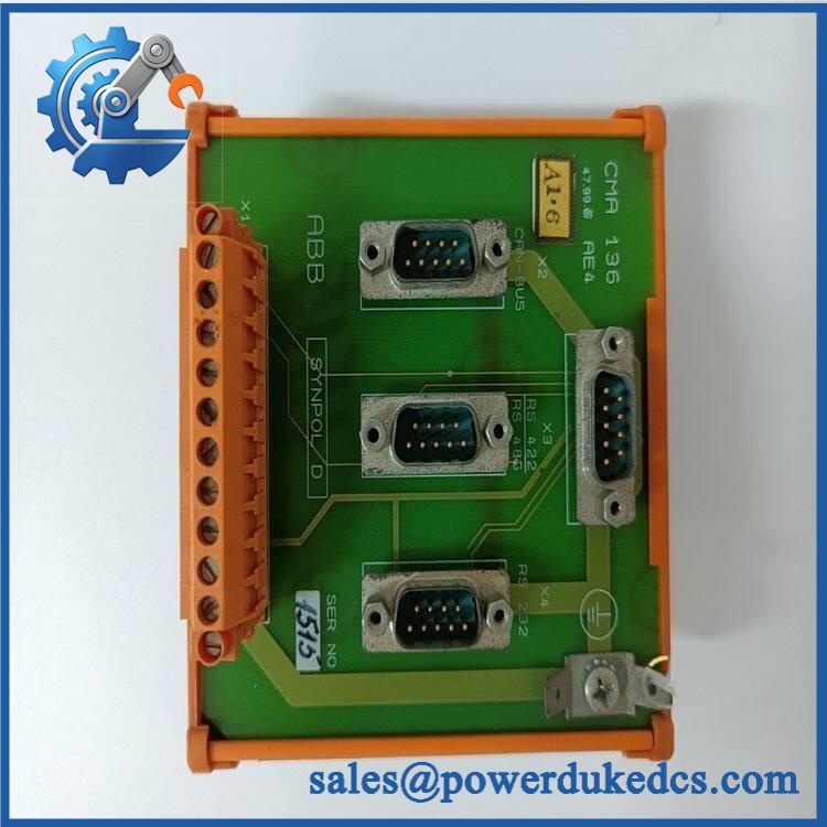
GE CM400RGICH1ACB
Application Scenarios & Pain Points
Micro-case — the safety controller remains powered but the gateway/interface function becomes unavailable. A maintenance team may see loss of status exchange or diagnostic communication while other cabinet equipment remains energized. In that situation, the CM400RGICH1ACB becomes a candidate only after power, network, and associated controller paths have been checked.
For turbine-control installations, commercial descriptions associate the part with Mark VIeS safety-control equipment, where redundant controller hardware is used for safety-related functions. Exact application approval should be based on the project configuration rather than a generic Mark VIeS product label.
Within plant safety systems, communication loss can be more difficult to isolate than an ordinary I/O fault because the module may sit between processing logic and external systems. Check Ethernet, serial connections, power distribution, and controller diagnostics independently before replacing the hardware.
At cabinet temperatures above 50°C, thermal margin deserves direct measurement. One commercial source gives a +70°C upper operating limit, but the correct value for the installed revision should come from the GE equipment documentation.
🚨 Common Error Codes & Diagnostic Symptoms
No reliable standalone numerical fault-code list specific to CM400RGICH1ACB was identified in the reviewed public documentation. Diagnosis should therefore use controller status, network diagnostics, power measurements, and host-system alarms.
Symptom/Code: Controller communication lost → Diagnosis: Possible DC supply loss, Ethernet/serial path failure, controller hardware fault, or configuration mismatch. → Action: Verify supply and external communication paths first; replace the module only after the fault is localized.
Symptom/Code: Repeated controller restart or watchdog condition → Diagnosis: Possible unstable power, thermal stress, firmware corruption, or processor hardware failure. → Action: Capture firmware and diagnostic information, verify the power source, then replace the controller when the fault follows the hardware.
Symptom/Code: Safety-system gateway unavailable while field I/O remains active → Diagnosis: Possible internal controller-interface failure or communication subsystem fault. → Action: Separate the network-path test from the controller test and confirm whether the failure remains after known-good communications hardware is substituted.
🚨 Cross-Reference & Lifecycle Migration
Cross-Reference
No authoritative GE document was located that establishes a direct replacement number for .
Related commercial records contain other CM400RGI and CM400RGA identifiers, but the available evidence does not establish that those models are direct replacements.
For replacement approval, compare:
- Full catalog number
- Hardware revision
- Connector arrangement
- Host Mark VIeS configuration
- Firmware revision
- Cabinet slot
- Power-input arrangement
- Safety certificate reference
Firmware Requirement
Firmware verification may be required.
A controller-level module can depend on a specific firmware and configuration baseline. Before removal of the existing unit, record the firmware version, serial number, network configuration, and applicable application image where the system permits access.
Do not install a replacement and assume that the latest available firmware is automatically appropriate for the existing safety-control configuration.
Lifecycle Status
Status: Legacy / Service Inventory — verify factory availability
The exact remains available through secondary industrial automation channels, but the reviewed sources do not establish current unrestricted factory production status.
For buffer-stock planning, maintain the complete part number and revision in the ERP item. Do not group together with other CM400-series assemblies without a documented engineering equivalency.
Field Engineer’s Tech Notes
Warning 1 — Photograph the nameplate before removing the controller.
Record the part number, revision, serial number, firmware information, and certification markings. A generic CM400-series designation is not enough for a safety-system replacement.
Warning 2 — Check the power source and communications path before condemning the module.
A controller that appears offline can be affected by a failed DC distribution fuse, loose terminal, Ethernet path, or upstream network device. Separate those checks first (it prevents unnecessary removal of safety-system hardware).
Strict QA & Testing SOP
Step 1 — Identity verification
Confirm the exact marking and photograph the nameplate, revision, serial number, and certification marks.
Step 2 — Mechanical inspection
Check the enclosure, mounting hardware, backplane connector, terminal interfaces, labels, and ventilation surfaces for cracks, contamination, corrosion, or impact damage.
Step 3 — ESD handling
Place the assembly on a grounded ESD workstation before exposing connectors or internal electronics.
Step 4 — Power pre-check
Verify the intended test voltage from the applicable GE system documentation. Do not use a reseller-stated 24 VDC value as the sole engineering basis for powering an unknown revision.
Step 5 — Controlled startup
Install the module in a compatible test environment and observe startup behavior, status indicators, diagnostic state, and communication initialization.
Step 6 — Firmware capture
Record the installed firmware and software identification. Compare it with the target system baseline.
Step 7 — Communication testing
Verify the applicable Ethernet and serial interfaces using a known-good test network and approved configuration.
Step 8 — Controller function test
Check processor startup, diagnostic reporting, communication stability, and controller-state behavior under controlled operating conditions.
Step 9 — Redundancy testing
Where the approved test system supports redundant operation, verify the required channel health and diagnostic behavior without connecting the unit directly to a live safety process.
Step 10 — Extended powered observation
Monitor for resets, communication loss, abnormal temperature, or intermittent diagnostic changes during an extended test.
Step 11 — Documentation
Record all measured values, firmware information, photographs, test equipment, serial data, and QA disposition.
Step 12 — Final packaging
Use ESD shielding material, mechanical cushioning, connector protection, and a rigid outer carton. Record final packed dimensions and gross weight for freight documentation.
Test videos are available for applicable units after successful testing on a compatible control-system test platform.
Buyer’s FAQ
Can I hot-swap the ?
Do not assume that capability. This is described as a controller/interface assembly associated with safety-control equipment, and replacement may affect controller state and safety functions. Follow the approved GE maintenance procedure and place the system in its defined safe maintenance condition before removal.
How do I verify a New Original ?
Request photographs of the actual unit, including the GE part number, hardware revision, serial number, connector arrangement, front indicators, and packaging. For safety-related hardware, also request applicable certificate information and the actual firmware revision.
What HS tariff code should be used?
The final HS/HTS classification depends on the importing country’s tariff schedule and the verified function of the actual assembly. The sources reviewed do not provide a sufficiently authoritative classification for the exact part number.
For customs documentation, describe the item by its verified function and have the importing-country customs broker confirm the final national tariff code.
Does the module include the latest firmware?
That cannot be established from the catalog number alone. Firmware is configuration-dependent for controller hardware, and the appropriate version may be determined by the installed Mark VIeS control-system baseline.
Record the firmware version from the actual replacement unit before commissioning.
What warranty should I expect?
Warranty depends on the supplier’s written terms and the condition category of the unit. For this type of legacy controller, request the warranty period, functional-test scope, actual serial number, firmware information, certification evidence, and return conditions before purchase. A supplier warranty should not be represented as a GE factory warranty unless GE has explicitly documented that coverage.











 Start Chat


