

Description
- Model & Brand: GE Digital Energy / GE D20-D200 10BASE-T Media Interface Card, historically identified as P/N 526-2110.
- Physical Dimensions: GE’s original mechanical drawing gives approximately 174 × 100 × 36 mm (6.83 × 3.94 × 1.40 in). The drawing identifies two RJ45 interfaces and the internal EME connection.
- Estimated Shipping Weight: Approximately 0.25 kg / 0.55 lb for one documented 526-2110-CC board. Use actual packed weight for freight documents because carton, ESD protection, and cushioning can materially increase gross weight. (turn286443search4)
- What’s in the Box: Normally the 10BASE-T MIC card itself. The associated D20EME main board and 977-0298 interconnect cable are separate system components unless specifically included in the quoted kit.
- Network Connectors: Two RJ45 connectors, one for each independent 10BASE-T channel.
- Installation Position: GE’s mechanical drawing specifies installation in the left-most slot in the D20MX and D200 chassis for the documented assembly.
Product Introduction
The D20 MIC 10BASE-T is a physical Ethernet interface board for the GE D20/D200 substation controller platform. It does not function as an independent Ethernet controller. Instead, the MIC works with a compatible D20EME Ethernet/Memory Expansion module, carrying Ethernet power and signaling through the interconnect between the EME main board and the MIC.
Two independent 10BASE-T copper Ethernet channels are provided through RJ45 connectors. GE specifies CAT5-or-better UTP cabling for this media type in its D20/ technical overview. The board also has configurable jumpers for SQE test, link test, and jabber on each channel. That jumper configuration is not cosmetic; it directly changes Ethernet physical-layer behavior (which matters when replacing a c
Core Technical Specifications
| Parameter | Value |
|---|---|
| Manufacturer | GE Digital Energy / GE Energy |
| Product Family | D20 / Substation Controller |
| Product Type | Media Interface Card |
| Historical GE Part Number | 526-2110 |
| Product Description | D20 EME 10BASE-T Media Interface Card |
| Ethernet Standard | 10BASE-T |
| Ethernet Speed | 10 Mbps |
| Ethernet Channels | 2 independent channels |
| Network Connector | RJ45 |
| Cable Type | Twisted-pair UTP, CAT5 or better |
| Main System Interface | Internal connection to D20EME |
| Interconnect Cable | 977-0298 |
| VME Architecture | D20/ VME chassis |
| Jumper Functions | SQE Test, Link Test, Jabber |
| Channel 1 Jumpers | JP1 |
| Channel 2 Jumpers | JP2 |
| Default Jumper State | 7-8 installed on JP1/JP2; other positions open |
| Default SQE Mode | Disabled |
| Front Indicators | XMT, CLS, LTF, RCV, POL, JAB per channel |
| Approx. Dimensions | 174 × 100 × 36 mm |
| Approx. Unit Weight | 0.25 kg for one documented revision |
| Firmware | No independent user firmware package identified for MIC itself |
| Host Requirement | Compatible D20EME / D20EME2 architecture |
| Modern Replacement Reference | 526-2116 for the earlier 526-2110 in GE documentation |
| Mounting | VME chassis / specified MIC position |
| Lifecycle | Legacy / replaced |
GE’s documentation specifically identifies 526-2110 as the 10BASE-T Ethernet MIC and describes it as a dual interface for the Ethernet EME card in D20/ systems. The later guide explicitly states that 526-2110 has been replaced by 526-2116.,
Power and Thermal Note
The MIC does not have a separately stated field power input. GE’s documentation indicates that power and Ethernet signaling are carried from the main EME card to the MIC through the interconnect cable.
Accordingly, cabinet power calculations should be based on the complete D20EME + MIC assembly, not on an assumed standalone 24 VDC rating. The MIC’s small board envelope also should not be interpreted as a negligible thermal load without checking the overall D20/ chassis loading.
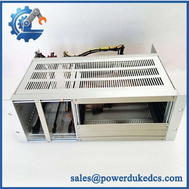
GE D20 MIC 10BASE-T
Application Scenarios & Pain Points
A substation RTU loses one Ethernet path while the D20 processor and field I/O continue running. The dual-channel MIC arrangement permits the physical Ethernet interfaces to be checked independently, making the MIC, RJ45 connections, EME interconnect, and upstream network equipment logical inspection points.
For utility communication networks, the 10BASE-T MIC provides two independent 10 Mbps copper Ethernet channels to the D20/ architecture. GE’s technical overview describes the D20EME Ethernet implementation as supporting direct connection to 10 Mbps Ethernet networks.
During legacy D20 migration, the MIC should not be evaluated separately from the EME main board. GE documents different compatibility combinations between 526-2100, 526-2101, 526-2102, and 526-2117 EME boards and the available MIC variants.
In an older control room with long copper Ethernet runs, physical-layer troubleshooting becomes important. The MIC has specific indicators for transmission, collisions, link-test failure, receive activity, polarity, and jabber, allowing technicians to distinguish several network conditions without immediately replacing the board.
At 50°C+ cabinet ambient, review the entire D20 chassis rather than the MIC alone. Temperature margin depends on the processor, EME boards, power supply, neighboring VME cards, and enclosure airflow.
🚨 Common Error Codes & Diagnostic Symptoms
This card does not use a PLC-style software fault-code database. GE instead provides per-channel Ethernet LED diagnostics.
Symptom/Code: LTF LED ON — Link Test Fail → Diagnosis: The Ethernet physical link is not being established correctly. Check the cable, hub/switch port, remote device, jumper configuration, and the MIC itself. → Action: Verify the complete physical link first; replace the MIC only when the failure follows the board.
Symptom/Code: POL LED ON — Polarity → Diagnosis: The MIC detects reversed receive polarity on the affected 10BASE-T channel. This can indicate cabling or termination problems rather than a failed PCB. → Action: Verify the twisted-pair cabling and remote Ethernet interface before replacing the card.
Symptom/Code: JAB LED ON — Jabber detected → Diagnosis: The transmitter has detected a jabber condition and disables transmission. The condition may originate from the connected network equipment or the MIC’s physical-layer circuit. → Action: Isolate the remote Ethernet equipment and cable; replace the MIC only if the condition remains with a known-good network path.
🚨 Cross-Reference & Lifecycle Migration
The most important documented cross-reference is direct from GE:
D20 EME 10BASE-T Media Interface Card, 526-2110 → replaced by D20 Media Interface Card EME 10BASE-T, 526-2116.
The system architecture also distinguishes the older and newer EME interfaces:
| Main EME Hardware | Compatible MIC |
|---|---|
| 526-2100 — , 8 MB + Ethernet | 526-2110 / related 10BASE-T option |
| 526-2101 — , Ethernet only | 526-2110 / related 10BASE-T option |
| 526-2102 — , memory only | No Ethernet MIC |
| 526-2117 — D20EME2 | 526-2116 / 526-2118 depending on media type |
GE’s compatibility table makes clear that 526-2110 and 526-2116 are associated with different generations of EME architecture. Therefore, “10BASE-T MIC” is not enough information for a replacement order.
Firmware
The MIC itself is a physical Ethernet media-interface assembly and is not documented as having a separately field-loaded application firmware package. Firmware/software is associated primarily with the D20/ processor and EME system architecture.
This distinction matters during replacement: a new MIC may still fail to operate correctly if the host EME hardware or D20 base software is incompatible. GE states that the main D20/ boards require appropriate CCU base software to access Ethernet or global-memory facilities over the VME backplane.
Lifecycle Status
Legacy / replaced. GE’s documentation explicitly states that 526-2110 has been replaced by 526-2116. Current GE documentation continues to identify the newer 10BASE-T MIC in the D20/ product family.
For buffer-stock planning, retain the old 526-2110 number and the newer 526-2116 reference together, but verify the EME main-board generation before issuing the newer card as a substitute.
Field Engineer’s Tech Notes
Warning 1 — Record JP1 and JP2 before removing the old MIC.
GE gives four defined jumper combinations for each 10BASE-T channel, affecting SQE test, link test, and jabber behavior. Do not assume the factory default is appropriate for every legacy network.
Warning 2 — Do not forget the EME interconnect cable.
The MIC receives its power and Ethernet signaling through the connection to the main board. GE specifies 977-0298 for the Ethernet kit, and the original mechanical drawing identifies J1 as the connection to the . A loose or incorrect interconnect can make a good MIC appear completely dead.
Strict QA & Testing SOP
Step 1 — Exact identity verification
Record the physical board number, revision, and any secondary assembly number. For legacy inventory, distinguish 526-2110 from 526-2116.
Step 2 — Mechanical inspection
Inspect the PCB, housings, card edge/interface, mounting hardware, jumper headers, LEDs, and board support points.
Step 3 — Connector inspection
Check both connectors and the EME interconnect for bent contacts, oxidation, contamination, cracked housings, or poor mechanical retention.
Step 4 — Jumper documentation
Capture JP1 and JP2 positions before energization. Compare them with the original site configuration.
Step 5 — ESD-controlled installation
Handle the board with grounded ESD precautions and install it only into the compatible D20/ chassis and EME architecture.
Step 6 — Power/interface verification
Confirm the EME main board and 977-0298 interconnect cable are correct before applying power.
Step 7 — Link test
Connect a controlled 10BASE-T test network and verify both channels independently.
Step 8 — LED diagnostic test
Check XMT, CLS, LTF, RCV, POL, and JAB indicators on both channels. Record the normal state for the test setup.
Step 9 — Jumper-function verification
Where test equipment permits, verify SQE test, link test, and jabber behavior against the selected JP1/JP2 configuration.
Step 10 — Network stability test
Operate both Ethernet channels continuously under representative traffic and monitor packet loss, link stability, collisions, and abnormal LED activity.
Step 11 — Host-system test
Install the MIC with the compatible board and verify that the D20/ system recognizes and communicates through the Ethernet interface.
Step 12 — Configuration record
Record EME main-board number, MIC number/revision, jumper configuration, cable P/N, chassis number, and network test result.
Step 13 — Final packaging
Place the accepted MIC in ESD shielding packaging with rigid protection around the connectors and board edges.
Test videos are available for qualifying inventory when pre-shipment evidence is required.
Buyer’s FAQ
Q1. Can I hot-swap the D20 MIC 10BASE-T?
Do not assume live replacement is permitted. The MIC is part of the D20/ VME architecture, and the correct procedure depends on the specific chassis and system configuration.
For routine maintenance, isolate the applicable equipment and follow the approved D20/ card-replacement procedure.
Q2. How do I verify a New Original unit?
Check the actual PCB marking and revision, not just the phrase “D20 MIC 10BASE-T.” The historical GE part number for the original 10BASE-T MIC is 526-2110, while GE later documented 526-2116 as its replacement.
Ask for photographs of both interfaces, the JP1/JP2 jumpers, the board label, and the complete connector area.
Q3. What warranty should be specified?
Warranty is supplier-specific for this legacy component. For New Surplus or refurbished inventory, specify the exact condition and require the warranty duration in writing.
For a critical substation spare, also require a functional Ethernet test record rather than relying solely on a power-up confirmation.
Q4. Does the D20 MIC 10BASE-T include the latest firmware?
The MIC is not normally treated as an independently firmware-loaded processor. Its function depends on the compatible /EME2 main board, interconnect cable, chassis, base software, and jumper configuration.
Lifecycle & Asset-Control Note
The GE D20 MIC 10BASE-T is the legacy dual-channel 10BASE-T Media Interface Card, historically identified as 526-2110. GE explicitly documents 526-2116 as the replacement for 526-2110, while the original board’s mechanical drawing specifies two ports and installation in the designated D20/ chassis position.,
For warehouse control, record D20 MIC 10BASE-T + 526-2110 + board revision + compatible EME main-board number + 977-0298 cable requirement + JP1/JP2 configuration + COO + certification evidene + QA result + storage condition. Do not issue 526-2116 as an automatic replacement without first checking the host EME generation.











 Start Chat


