

Description
- Model & Brand: GE DigitalFlow XMT868i, now associated with the Panametrics product line under Baker Hughes.
- Product Type: Ultrasonic liquid flow transmitter using Correlation Transit-Time™ measurement technology. The instrument is available in single-channel and optional two-channel configurations.
- Standard Housing: Epoxy-coated aluminum, approximately 208 mm × 168 mm; published standard-unit weight is approximately 4.5 kg / 10 lb.
- Optional Stainless-Steel Housing: Approximately 13.6 kg / 30 lb for the heavier enclosure configuration.
- What’s in the Box: Normally the XMT868i transmitter electronics/enclosure. Transducers, signal cables, flowcell hardware, mounting hardware, power-disconnect equipment, and optional I/O boards should be confirmed separately against the actual order configuration.
- Power: Standard 95–240 VAC, 50/60 Hz, ±10%; optional 12–28 VDC, ±5%. Maximum power consumption is 20 W.
- Display: Optional 2-line × 16-character backlit LCD with six-button infrared keypad.
- Field Interfaces: Standard isolated 0/4–20 mA outputs, RS232 service communications, with optional RS485, Modbus, Ethernet, HART, Foundation Fieldbus, analog inputs, RTD inputs, frequency outputs, and alarm relays depending on option-card configuration.
Product Introduction
For hazardous-area liquid measurement, the transmitter enclosure is part of the installation design, not simply a protective shell. The GE DigitalFlow XMT868i uses an epoxy-coated aluminum or optional stainless-steel housing and is documented for hazardous environments, including Class I Division 1 and flameproof applications. Its enclosure is specified to IP66, while the approved ambient range is -40°C to +60°C.
The measurement engine is based on Correlation Transit-Time™ ultrasonic technology. Standard hardware is single-channel; a two-channel version is available for two pipes or two measurement paths on one pipe. Published performance data gives a velocity range of approximately -12.2 to +12.2 m/s, overall rangeability of 400:1, and repeatability of approximately ±0.1% to ±0.3% of reading. With suitable process calibration and a properly developed flow profile, the instrument can achieve approximately ±0.5% of reading velocity accuracy.
Core Technical Specifications
| Parameter | Value |
|---|---|
| Manufacturer / Brand | GE / Panametrics |
| Product Family | DigitalFlow |
| Exact Model | XMT868i |
| Product Type | Ultrasonic liquid flow transmitter |
| Measurement Principle | Correlation Transit-Time™ |
| Channel Configuration | 1 channel standard; 2 channel optional |
| Measurement Arrangement | 2 pipes or 2 paths per pipe for dual-channel configuration |
| Measured Media | Acoustically conductive liquids |
| Standard Flow Mode | Transit-Time |
| Velocity Range | -12.2 to +12.2 m/s |
| Overall Rangeability | 400:1 |
| Repeatability | ±0.1% to ±0.3% of reading |
| Calibrated Velocity Accuracy | Up to approximately ±0.5% of reading |
| Clamp-On Accuracy, ID >150 mm | Typically ±1% to ±2% of reading |
| Clamp-On Accuracy, ID <150 mm | Typically ±2% to ±5% of reading |
| Typical Wetted Accuracy | Approximately ±1% of reading |
| Straight-Run Assumption | Typically 10 pipe diameters upstream / 5 downstream |
| Standard AC Power | 95–240 VAC, 50/60 Hz, ±10% |
| Optional DC Power | 12–28 VDC, ±5% |
| Maximum Power Consumption | 20 W |
| Standard Analog Outputs | 2 isolated 0/4–20 mA |
| Analog Output Load | 600 Ω maximum |
| Optional Analog Inputs | 2 isolated 0/4–20 mA inputs with 24 VDC loop power |
| Optional RTD Inputs | 2 or 4 isolated 3-wire RTD inputs |
| Optional Frequency Outputs | 2 or 4 isolated pulse/frequency outputs |
| Serial Communications | RS232 standard |
| Optional Serial Communications | RS485 |
| Ethernet | Optional |
| Protocol Options | Modbus RTU / Modbus TCP and other configuration-dependent interfaces |
| Display | 2-line × 16-character LCD, optional |
| Keypad | Six-button infrared keypad |
| Housing | Epoxy-coated aluminum standard |
| Optional Housing | Stainless steel |
| Standard Housing Protection | Type 4X / IP66 |
| Hazardous Location | Class I Div. 1 / Class II / Class III and flameproof variants documented |
| Operating Temperature | -40°C to +60°C |
| Storage Temperature | -55°C to +75°C |
| Standard Housing Weight | 4.5 kg / 10 lb |
| Stainless Housing Weight | 13.6 kg / 30 lb |
| Standard Housing Reference Size | 208 × 168 mm |
| Software | PanaView and related XMT868i configuration tools |
| Memory / Program Storage | Internal meter program/data memory; exact capacity is configuration-dependent |
| Lifecycle | Retired / legacy |
The published specification set identifies 20 W maximum consumption, the two power-supply options, single- or dual-channel architecture, Type 4X/IP66 enclosure, and the documented temperature and weight values.
Power and Thermal Note
At maximum stated consumption, the XMT868i can require approximately 20 W of electrical input. The enclosure therefore needs ordinary industrial thermal review, particularly when several transmitters are installed together inside a cabinet or when the electronics enclosure is exposed to high ambient conditions.
For the DC-powered version, GE specifies a 12–28 VDC supply with ±5% tolerance and notes that a Class 2-rated supply is required. Do not substitute an arbitrary 24 VDC supply in a hazardous-area installation without confirming the applicable installation documentation.
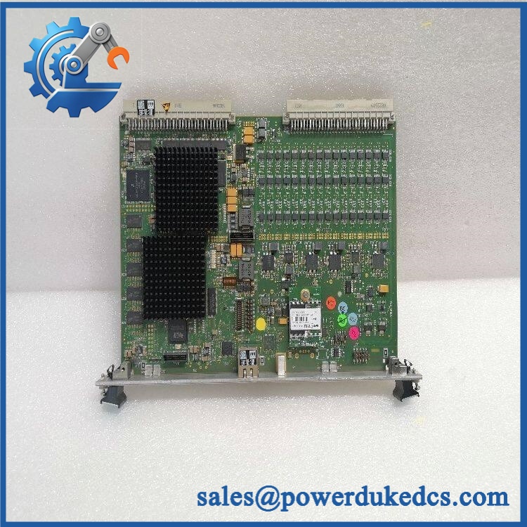
GE DIGITALFLOW XMT868I
Application Scenarios & Pain Points
A refinery needs permanent flow measurement on a process line where cutting the pipe is undesirable. The XMT868i can use clamp-on transducers, avoiding a conventional pipe penetration for the ultrasonic measurement itself. Panametrics also documents applications involving hydrocarbon liquids, crude oil, lubricating oils, diesel fuel, solvents, water, wastewater, chemicals, beverages, and other liquids.
For two-path metering, the dual-channel configuration can be used either on two separate pipes or on two paths through the same pipe. That architecture can improve measurement coverage where flow profile effects need to be considered.
In petrochemical service, the transmitter can be installed in hazardous locations using the applicable approved enclosure and certification configuration. The documented markings include Class I Division 1 and flameproof Ex d arrangements with IP66 protection.
For energy-measurement applications, optional analog and RTD input boards can be used to collect temperature data for energy calculations. This requires the corresponding hardware option; a standard XMT868i should not be assumed to contain the RTD or analog-input boards.
At a 50°C+ ambient condition, the transmitter remains within the documented continuous operating envelope up to +60°C, but there is little thermal margin left. Cable glands, enclosure loading, direct solar exposure, and adjacent heat sources should be reviewed before approving the installation.
🚨 Common Error Codes & Diagnostic Symptoms
The XMT868i has a dedicated diagnostic/error-message system. These messages do not automatically indicate a failed transmitter; many are caused by transducers, cabling, fluid conditions, installation geometry, or incorrect setup parameters.
Symptom/Code: E1 – Low Signal → Diagnosis: Ultrasonic signal strength is too low, or the signal exceeds the limits programmed in the setup. GE lists defective cables, flowcell problems, defective transducers, electronics-console faults, and incorrect setup values as possible causes. → Action: Check transducer condition, cable integrity, coupling/flowcell condition, and signal setup before replacing the electronics.
Symptom/Code: E2 – Sound Speed Error → Diagnosis: Measured sound speed is outside the programmed limits. Incorrect fluid data, poor flow conditions, or improper transducer orientation can all create the condition. → Action: Verify fluid parameters, flowcell/transducer alignment, and process conditions before condemning the transmitter.
Symptom/Code: E4 – Signal Quality → Diagnosis: Signal quality is outside the configured limits. This commonly points toward coupling, transducer alignment, fluid characteristics, pipe condition, or signal-path problems rather than a processor failure. → Action: Inspect the ultrasonic path and installation parameters first; replace the electronics only after those causes are eliminated.
Symptom/Code: E13 – Volumetric Overflow → Diagnosis: The calculated volumetric or mass-flow value has exceeded the programmed calculation range, causing a mathematical overflow. → Action: Correct the configured measurement units or time interval rather than replacing the transmitter.
🚨 Cross-Reference & Lifecycle Migration
The XMT868i is a configuration-sensitive measurement platform. A basic one-channel AC-powered unit is not necessarily equivalent to a two-channel, DC-powered, hazardous-area, HART, Modbus, Foundation Fieldbus, or RTD-equipped version.
Important configuration variables include:
- One or two ultrasonic channels.
- AC or DC power supply.
- Aluminum or stainless-steel enclosure.
- Analog input and RTD option cards.
- Frequency-output and alarm-relay options.
- RS485, Modbus, Ethernet, HART, or Foundation Fieldbus options.
- Hazardous-area certification package.
- Clamp-on versus wetted transducer arrangement.
The published service documentation also shows field-replaceable circuit-board assemblies, including the LCD/interconnect board, analog/RTD boards, frequency-output boards, EPROM-related assemblies, and power-supply circuitry. That means the internal hardware configuration should be recorded, not only the outer model name.
Predecessor and Successor
The XMT868 series has a long installed base. A current Panametrics distributor record identifies the PanaFlow XMT1000 as the recommended replacement for the XMT868i and states that the XMT868i range was officially discontinued in August 2020. This is consistent with current market records categorizing the XMT868i as retired, although Baker Hughes continues to host XMT868i manuals and product documentation.
This should be treated as a migration path, not a direct drop-in replacement statement. The newer transmitter can require changes to wiring, transducers, configuration, mounting, communications, or hazardous-area documentation.
Firmware / Software
The XMT868i uses internal program/data memory and supports configuration through PanaView and the instrument’s front-panel programming functions. The service manual also documents EPROM replacement and testing in the earlier hardware architecture.
For legacy replacement work, capture:
meter software/firmware revision + site data + transducer configuration + I/O option cards + communications settings.
Do not assume that a newer software image can be loaded onto every historical XMT868i hardware configuration.
Lifecycle Status
Retired / Legacy. Current market records identify the XMT868i as retired, and Panametrics identifies the newer XMT1000 as the replacement path. Baker Hughes continues to provide XMT868i manuals and documentation, so service information remains accessible even though normal new-product purchasing has moved to newer generations.
For buffer stock, retain application-specific spares where the existing transmitter is installed in a hazardous area or where transducer compatibility makes rapid replacement difficult.
Field Engineer’s Tech Notes
Warning 1 — Do not start by replacing the electronics when E1 appears.
The XMT868i service documentation specifically lists the transducer, cable, flowcell, and electronics console as possible causes of low signal. Check the ultrasonic path first.
Warning 2 — Match transducer cable lengths carefully.
GE specifies that, for transducers below 2 MHz, cable lengths should be within 4 in. / 10 cm of one another; above 2 MHz, the difference should be within 0.5 in. / 1.25 cm. This is a small detail with real effect on ultrasonic signal performance (especially during a replacement where old cables are reused).
Strict QA & Testing SOP
Step 1 — Identity inspection
Record the complete XMT868i model designation, serial number, enclosure material, channel count, power-supply type, certification markings, and option-card configuration.
Step 2 — Physical inspection
Inspect the enclosure, cover threads, grounding point, cable glands, terminal blocks, display, keypad, mounting hardware, and transducer connections for damage or corrosion.
Step 3 — Certification-label verification
Photograph all hazardous-area and regulatory markings. The documented XMT868i markings can include FM approval, Class I Division 1, Class I Zone 1, ATEX, IECEx, Ex d, and IP66 depending on the certified configuration.
Step 4 — Power-supply test
Verify the actual unit against its nameplate. For AC versions, use the documented 95–240 VAC class supply; for DC versions, use 12–28 VDC within the specified tolerance and approved supply arrangement.
Step 5 — Display/keypad test
Where the LCD/keypad option is installed, verify display readability, backlight operation, six-button keypad response, and menu navigation.
Step 6 — Analog-output test
Test each installed 0/4–20 mA output using a calibrated current meter. GE documents two isolated standard outputs with a 600 Ω maximum load.
Step 7 — Communication test
Verify RS232 service communications and any installed RS485, Modbus, Ethernet, HART, or Foundation Fieldbus option according to the actual configuration.
Step 8 — Transducer-path test
Use known-good compatible transducers and correct signal cables. Confirm that channel activation, signal strength, sound-speed measurement, signal quality, and flow calculation all operate normally.
Step 9 — Flow-signal simulation / controlled-flow test
Where a calibrated flow facility is available, compare measured velocity and flow against the reference standard. Document pipe parameters, fluid conditions, transducer arrangement, and flow direction.
Step 10 — Error-diagnostic test
Verify the instrument can detect representative diagnostic conditions without creating unsafe operating states. Record E1, E2, E4, E7, E8, E9, and E13 behavior where the approved test procedure supports it.
Step 11 — Data and configuration capture
Save the site configuration, transducer parameters, I/O scaling, communications settings, and software/firmware information.
Step 12 — Thermal observation
Run the transmitter under representative operation and monitor enclosure temperature. Check that the equipment remains within the documented -40°C to +60°C operating range.
Step 13 — Final preservation
Protect cable glands, terminal interfaces, display face, and enclosure threads. Use suitable moisture-resistant and ESD-conscious packaging.
Step 14 — Documentation
Record serial number, certification label, option cards, test conditions, diagnostic results, and final QA disposition.
Test videos are available for qualifying inventory when pre-shipment inspection evidence is required.
Buyer’s FAQ
Q1. Can I hot-swap the XMT868i?
Do not assume live replacement is permitted. The transmitter may be installed in hazardous areas, and the enclosure can contain AC or DC power connections plus ultrasonic transducer wiring.
The startup documentation requires the main power to be disconnected before transducer wiring work. Use the site’s isolation procedure and the applicable hazardous-area work controls before opening the enclosure.
Q2. How do I verify a New Original XMT868i?
Request photographs of the actual transmitter nameplate and certification markings, then verify channel count, power supply, enclosure material, installed option cards, serial number, and transducer configuration.
This is particularly important for retired equipment because an externally similar XMT868i can contain materially different I/O and communication hardware.
Q3. What warranty should be specified?
Warranty should be defined by the supplier and the inventory condition. For a retired XMT868i, specify whether the unit is New Original, New Surplus, refurbished, or repaired, then state the warranty period and test coverage explicitly.
For critical flow points, a functional-test warranty is more useful than a generic power-up guarantee.
Q4. Does the XMT868i include the latest firmware?
Do not assume it does. The instrument has configuration- and revision-dependent internal program/data memory, and the service documentation covers firmware/program-memory related service procedures.
For replacement procurement, request the installed software/firmware revision, site configuration, transducer data, and option-card inventory before commissioning.
Lifecycle & Asset-Control Note
The GE DigitalFlow XMT868i is a retired Panametrics ultrasonic liquid flow transmitter, while Baker Hughes continues to publish the XMT868i technical and service documentation. Current market documentation identifies the PanaFlow XMT1000 as the newer replacement path.
For existing installations, the most important warehouse fields are:
XMT868i model + serial number + channel count + AC/DC power option + enclosure material + hazardous-area marking + I/O option cards + transducer type + firmware/software revision + site configuration + QA status.
That record provides a practical basis for preserving a legacy measurement point and evaluating a future migration to the XMT1000.











 Start Chat


