

Description
- Brand: GE
- Full Model Number: DS200DCFBG2BNC
- System/Series Family: GE Mark V / DC2000, AC2000 and related drive-control systems
- One-Sentence Core Function: DC power supply and feedback board providing control-level power, voltage/current feedback, and SCR firing-control circuitry
- Top 3 Hardcore Specs: +5 VDC and ±15 VDC control supplies; ±24 VDC supply circuitry; AC/DC voltage and current feedback with SCR gate-pulse generation
- Stock Status: New surplus / fully tested refurbished, subject to exact board revision
GE’s DCFB documentation identifies the board as a power supply board used in DC2000, CB2000, EX2000, FC2000, GF2000, ME2000, and AC2000 applications. The board receives control power and provides control-level supplies, motor-field circuitry, voltage/current monitoring, and SCR firing-control functions.
Module 3: Commercial-Technical Deep Dive
A DCFB failure can look like a drive-control failure because the board does far more than distribute low-voltage power. The GE DS200DCFBG2BNC belongs to the DCFB Power Supply Board family used throughout GE legacy drive and excitation architectures. Its functions include generating +5 VDC, ±15 VDC, and ±24 VDC control-level supplies, monitoring AC-line and DC-bus quantities, and supplying the circuitry used for SCR field/armature firing control. GE documentation also shows that line-voltage feedback is conditioned through configurable VCO circuits before being passed toward the SDCC/LDCC control electronics.
The engineering value is concentrated in one replacement board: power generation, feedback conditioning, and firing-control support are combined rather than distributed across several separate assemblies. The board also contains configurable switches, jumpers, fuses, transformers, and a programmed gate-array section; GE’s documentation notes that the gate array is programmed at power-up by a serial PROM. That makes configuration preservation critical. A replacement board with the same base catalog number still needs its switch and jumper settings checked against the original drive voltage, current-transformer burden, and feedback configuration before commissioning.
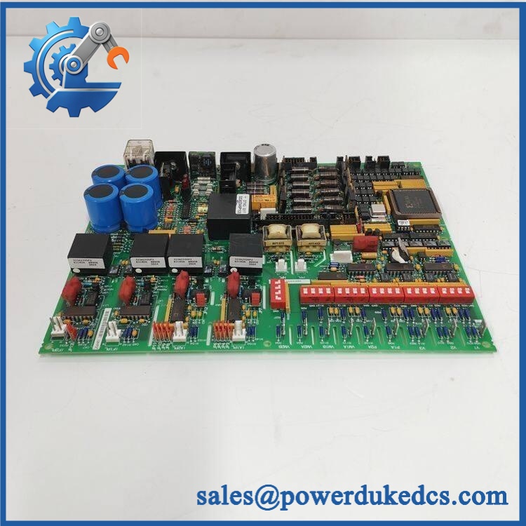
GE DS200DCFBG2BNC
Module 4: Compatibility & Installation Traps
Migration/Compatibility
- Replacement type: GE DCFB DC power supply and feedback board
- Model: DS200DCFBG2BNC
- Functional family: DCFB
- System/Series Family: GE Mark V and related DC2000/AC2000 drive platforms
- Firmware flash: Not normally applicable as a board-level replacement, although the onboard gate-array/PROM configuration is part of the board hardware.
- Logic rewrite: Not normally required for a correctly matched same-board replacement.
- Drop-in status: Potentially direct when the complete DS200DCFBG2BNC part number and application match.
- Revision check: GE’s DS200 numbering convention identifies functional and artwork revisions; GE documentation stresses that all digits are important when ordering or replacing a board.
⚠️ Field Traps (Watch Out)
1. Switch settings are application-specific.
The DCFB uses switches SW1 through SW3 for AC-line voltage scaling, while SW4 scales the DC-bridge feedback circuit. Additional switches configure current-transformer scaling and other application parameters. These settings must match the installed drive. An incorrect setting can produce incorrect feedback values or protection behavior even when the board powers up normally.
2. Check the three DCFB fuses before condemning the board.
GE documentation identifies FU1, FU2, and FU3 for different supply circuits. Indicator devices show when particular fuses have opened: FU2 is associated with the +24 VDC path to the +15 VDC regulator, FU3 with the −24 VDC path to the −15 VDC regulator, and FU1 with a 115 VAC circuit. A blown fuse may therefore be the symptom of a downstream fault rather than the root cause.
3. Verify the application before substitution.
The same DCFB family is used in multiple GE platforms, but the functional context differs. GE specifically notes that EX2000 uses the board differently from drive applications. Confirm whether the installed system is DC2000, AC2000, EX2000, or another supported architecture before applying generic drive settings.
4. Record every jumper and DIP-switch position before removal.
This board contains numerous configurable elements. Photograph the entire board before disconnecting it; do not reconstruct settings from memory after the replacement is installed.
Module 5: Quality Assurance SOP
Each GE DS200DCFBG2BNC unit should pass a documented pre-shipment inspection sequence:
- OEM anti-counterfeit visual inspection: Verify GE identification, DS200DCFBG2BNC marking, DCFB designation, PCB artwork, component population, connector geometry, and manufacturing labels.
- Part-number verification: Confirm every character of the complete catalog number against the purchase order and installed system BOM.
- Revision verification: Record the G2BNC revision/configuration marking and compare it with the original board where possible.
- Mechanical inspection: Check plug connectors, stab terminals, terminal pins, transformers, heatsinks, fuse holders, relay, jumpers, DIP switches, and PCB surfaces for damage, corrosion, contamination, or thermal discoloration.
- Fuse inspection: Check FU1/FU2/FU3 condition and verify that any replacement fuses are the correct type and rating for the application.
- Power-on self-test (POST): Test the board in an approved GE-compatible fixture, verifying generation of the expected control-level supply rails and checking for abnormal diagnostic indications.
- Feedback verification: Apply controlled simulated AC/DC feedback signals and confirm expected voltage/current feedback behavior at the test interface.
- SCR gate-control verification: Where the test rack supports it, verify the gate-control circuitry and expected firing-pulse behavior under a controlled low-energy test setup.
- Communication handshake verification: Not applicable as an Ethernet-style interface. The DCFB exchanges control signals with associated Mark V electronics through board-level and connector interfaces; system-level validation should confirm correct interaction with the SDCC/LDCC and associated drive hardware.
- Configuration verification: Confirm SW1–SW7 and jumper settings against the approved test configuration before release.
- Final QC: Photograph the part number and configuration settings, retain the test record, protect all connectors and components against ESD and impact, and package the board securely.
Module 6: CRO-Driven Buyer FAQ
1. What is GE ?
The is a GE DCFB Power Supply Board used in legacy GE drive and turbine-control-related architectures. Its functions include control-level power generation, voltage/current feedback conditioning, motor-field circuitry, and SCR firing-control support.
2. What systems use the DCFB board?
GE documentation identifies DCFB applications in DC2000, CB2000, EX2000, FC2000, GF2000, ME2000, and AC2000 systems. The exact board configuration and switch settings depend on the installed application.
3. Can the be hot-swapped?
Do not assume hot-swap capability. The board can interface with hazardous AC and DC circuits and contains power-supply and SCR firing-control circuitry. Replacement should follow the applicable GE maintenance procedure, with complete isolation and verification of the relevant energized circuits before removal.
4. What should be checked before installing a replacement board?
Verify the complete part number, application family, fuse arrangement, DIP-switch settings, jumper positions, feedback scaling, and associated control-board connections. GE’s manual specifically states that all digits in the board catalog number are important when ordering or replacing a board.
5. What warranty and technical support are provided?
Warranty duration should be stated on the quotation for the exact inventory condition supplied. Technical support should cover part-number verification, revision matching, switch/jumper configuration review, inspection/test documentation, and replacement guidance within the documented GE Mark V/drive architecture. High-voltage commissioning, SCR firing verification, field wiring, and energized troubleshooting require appropriately qualified personnel.











 Start Chat


