

Description
- Model: DS200DMCBG1AKG
- Brand: General Electric (GE)
- Series: Mark V DS200 / EX2000
- Part Type: IOS DUP Processor Board
- Functional Acronym: DMCB
- Core Function: Provides the main control-processing and interface functions for compatible GE IOS/IOS+ and related Mark V turbine-control equipment.
- Key Specs: 3 × 26-pin connectors, 1 × 40-pin connector, 19 jumpers, 2 LED indicators, and a board-mounted reset switch. The exact revision string is A / K / G: Functional Revision 1 = A, Functional Revision 2 = K, Artwork Revision = G.
Product Introduction
During a Mark V control outage, a failed DMCB can affect controller initialization, operator-interface communication, and several system-level control functions at once. The GE DS200DMCBG1AKG is identified as an IOS DUP Processor Board and carries the DMCB functional designation. GE Mark V documentation and legacy equipment records place this board within the turbine-control ecosystem used for gas, steam, and wind turbine applications.
This is a configuration-sensitive legacy processor board. The board carries 19 jumpers, multiple connectors, a reset switch, and several visible identification labels; some jumper positions are intended for factory testing and should not be changed in the field. The exact A/K/G revision structure should remain in the warehouse record because board layouts and component positions can differ between revisions (do not normalize the item to “DS200DMCBG1A” without preserving the full suffix).
Core Technical Specifications
| Parameter | Value |
|---|---|
| Manufacturer | General Electric (GE) |
| Part Number | DS200DMCBG1AKG |
| Series | Mark V DS200 |
| Associated System | EX2000 / Mark V turbine-control architecture |
| Functional Description | IOS DUP Processor Board |
| Functional Acronym | DMCB |
| Functional Revision 1 | A |
| Functional Revision 2 | K |
| Artwork Revision | G |
| PCB Coating | Normal coating |
| Main Board Label | “IOS Main Control” reported |
| 26-Pin Connectors | 3 |
| 40-Pin Connector | 1 |
| LED Indicators | 2 |
| Reset Switch | 1 surface-mounted reset switch |
| Total Jumpers | 19 |
| Accessible Plug References | 1PL through 4PL reported |
| Additional Connector Reference | ARCPL reported |
| Processor | Exact CPU device not verified from reliable part-specific OEM documentation |
| Memory | Exact installed RAM/ROM capacity not verified |
| Firmware | System/board firmware is configuration-dependent; actual revision must be checked on the unit |
| Ethernet | Not established as an independent board interface |
| Standalone Fieldbus | Not established from the reviewed part-specific records |
| User Application Memory | Not independently verified |
| Power Input | Supplied through the associated Mark V/EX2000 architecture; exact board-level input not verified |
| Operating Temperature | Exact OEM value for this specific revision not verified |
| Storage Temperature | Exact OEM value not verified |
| Exact Board Dimensions | OEM mechanical drawing not verified |
| Exact Net Weight | OEM net weight not verified |
| Lifecycle | Legacy / discontinued Mark V hardware |
The exact-part technical record confirms the three 26-pin connectors, one 40-pin connector, two LEDs, reset switch, and 19 jumpers. It also identifies the unit as an IOS DUP Processor Board with A/K/G revision designations and normal PCB coating.
One secondary commercial listing gives a packaged size of approximately 16 × 16 × 12 cm and a shipping weight around 1 kg for the related DMCB board family, but that information is not sufficiently controlled to be treated as an OEM net-weight or dimensional specification for the exact DS200DMCBG1AKG. Use the physical unit for freight calculations.
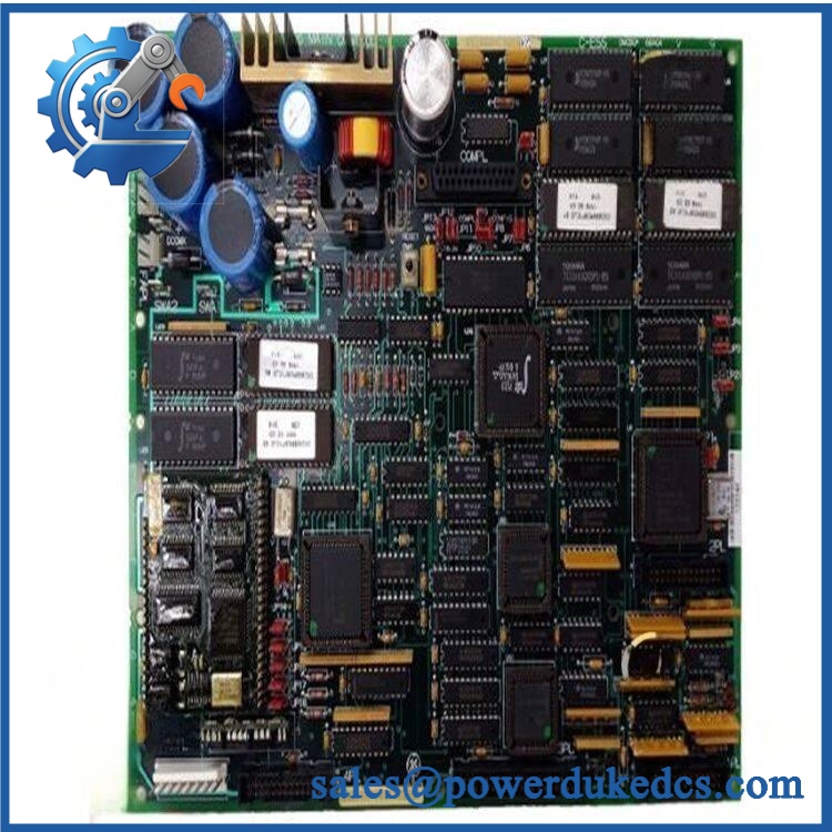
GE DS200DMCBG1AKG
Application Scenarios & Pain Points
Micro-case — controller startup fails after a DMCB fault. A processor-board problem may present as loss of associated operator display, failure to initialize, or an unexpected Mark V control state. External power and connected interface boards should be checked before the DMCB is condemned.
Within EX2000 and related Mark V installations, the DMCB serves as a central control and processing assembly. GE-related records describe the DMCB architecture as interfacing with operator keypad/display functions, DLAN communication, optional ARCNET-based DLAN+, optional Genius LAN hardware, RS-232C communications, and local I/O interface boards. These functions are documented for the broader DS200 DMCB family rather than as independent specifications for every revision.
During legacy migration, the full board suffix matters. The exact unit is A/K/G, while other DMCB variants use different suffixes such as ABA, ABB, ACB, AED, AFD, AGE, AJE, and ALG. Current legacy inventories list these as separate assemblies, so a partial part-number match is not enough for release to maintenance.
At cabinet temperatures approaching 50°C, inspect the board, connectors, memory devices, and surrounding airflow path carefully. A verified exact-revision environmental specification was not established in the reviewed material, so the installed Mark V/EX2000 system environmental limit should govern.
🚨 Common Error Codes & Diagnostic Symptoms
The DMCB is a processor board and does not have a modern universal numeric fault-code table for independent board diagnosis. Mark V controller states, LEDs, operator display behavior, and system diagnostics provide the practical fault evidence.
Symptom/Code: Mark V fails to initialize after DMCB replacement → Diagnosis: Possible revision, firmware, memory, jumper, or system-configuration mismatch rather than immediate PCB failure. → Action: Compare the replacement board with the original configuration, verify approved jumper positions and firmware state, then repeat controlled initialization.
Symptom/Code: Processor board appears powered but operator display or control interface remains unavailable → Diagnosis: Possible DMCB processing fault, connector problem, reset-state issue, or failure in a dependent interface board. → Action: Check the connected control interfaces and board connectors before replacing the DMCB.
Symptom/Code: Intermittent control restart / unstable controller operation → Diagnosis: Possible power instability, marginal connector contact, thermal stress, or processor-board hardware degradation. → Action: Verify the supply path and connectors, capture the controller state, and replace the DMCB when the fault follows the board.
🚨 Cross-Reference & Lifecycle Migration
Cross-Reference
The exact model belongs to the broader DS200DMCB family. Current legacy inventories list related variants such as:
- DS200DMCBG1A
- DS200DMCBG1ABA
- DS200DMCBG1ABB
- DS200DMCBG1ACB
- DS200DMCBG1AED
- DS200DMCBG1AFD
- DS200DMCBG1AGE
- DS200DMCBG1AJE
- DS200DMCBG1AKG
- DS200DMCBG1ALG
These are separate part identities in legacy inventories. A similar DMCB designation does not establish a universal drop-in replacement.
A later DS215DMCBG1AZZ03A assembly is also commercially associated with DS200DMCBG1AED and DS200DMCBG1AKG in replacement listings. That relationship should be treated as a migration/search reference only until the target Mark V application and firmware configuration are confirmed.
Firmware Requirement
Firmware matching may be required.
The DMCB family is associated with firmware/software stored on nonvolatile devices in the Mark V control architecture. Related GE inventory records explicitly identify separate EEPROM assemblies, including EEPROM versions containing firmware.
Before removing the original DMCB, record:
- Installed firmware revision
- EEPROM/EPROM device markings
- Jumper positions
- Board revision
- Associated control-system configuration
- Operator-interface and communication configuration
Do not alter or replace memory devices until the approved migration procedure has been documented.
Lifecycle Status
Status: Obsolete / Legacy
The Mark V platform is described in current legacy inventory records as discontinued, although specialist service inventories continue to carry DMCB variants.
For buffer-stock management, store the and preserve the actual board’s jumper and memory configuration. A generic “Mark V processor board” inventory item is too broad for outage control.
Field Engineer’s Tech Notes
Warning 1 — Do not move every jumper to match a different board position.
GE-related technical records note that some jumper positions can differ because of board revisions. Match the jumper identifier and pin position, not simply the visual location of the jumper on the replacement PCB. Some jumpers are intended for factory testing and should remain untouched.
Warning 2 — Capture the memory devices before removal.
The DMCB family is closely tied to firmware and configuration memory. Photograph every EEPROM/EPROM marking and its socket location before the old board leaves the cabinet. This is a small step that can prevent a much longer commissioning investigation.
Strict QA & Testing SOP
Step 1 — Exact identity check
Confirm and record the A/K/G revision structure, serial information, date/lot information, and all secondary labels.
Step 2 — PCB inspection
Inspect the board for corrosion, thermal discoloration, damaged ICs, cracked solder joints, bent pins, contamination, and evidence of unauthorized repair.
Step 3 — Connector inspection
Inspect all three 26-pin connectors and the 40-pin connector for bent contacts, cracked housings, oxidation, and solder-joint damage.
Step 4 — Jumper documentation
Photograph all 19 jumpers and record their positions exactly. Identify field-configurable jumpers separately from factory-test jumpers.
Step 5 — Reset-switch inspection
Check the surface-mounted reset switch for mechanical damage and reliable actuation. Do not repeatedly cycle it without following the applicable service procedure.
Step 6 — Memory inspection
Record all visible EEPROM/EPROM device markings and socket positions. Compare them with the target Mark V configuration.
Step 7 — Electrical pre-check
Perform controlled resistance and continuity checks only at documented test points. Do not apply a guessed supply directly to an unidentified PCB input.
Step 8 — Controlled power-up
Install the board in an approved compatible Mark V/EX2000 test environment and observe startup behavior, LEDs, reset state, and controller initialization.
Step 9 — System-interface testing
Verify applicable operator-interface, RS-232C, DLAN, and other installed communication/interface functions according to the specific control architecture. The precise interface set depends on the host system and optional hardware.
Step 10 — Extended run test
Operate the board under controlled conditions and monitor for processor resets, communication loss, abnormal heating, or unstable controller states.
Step 11 — Configuration validation
Compare the test unit’s firmware, memory, jumper configuration, and controller behavior with the target system baseline.
Step 12 — Documentation
Record serial number, revision, memory data, jumper positions, measured values, test results, photographs, and QA disposition.
Step 13 — Final ESD packaging
Place the board in ESD shielding material, protect every connector, and use rigid cushioning to prevent PCB flex during transport.
Test videos are available for applicable units tested on a compatible Mark V/ platform.
Buyer’s FAQ
Can I hot-swap the ?
Do not assume hot-swapping is permitted. This is a processor-level Mark V board connected to the control system’s power, communications, and interface hardware. Use the approved GE maintenance procedure and isolate the relevant power before removal.
How do I verify a New Original ?
Request photographs of the actual PCB, showing the complete part number, A/K/G revision markings, connectors, 19-jumper arrangement, reset switch, LEDs, memory devices, and packaging. For a legacy processor board, those details provide much stronger identity evidence than a generic product photograph.
Does a newer DMCB revision replace ?
The DMCB family contains numerous suffix variants, and commercial records also associate DS215DMCBG1AZZ03A with some DS200DMCB assemblies. These relationships are not sufficient to establish a universal direct replacement. Match the complete revision and Mark V/ system configuration before approving a migration.
What HS tariff code should be used?
The final HS/HTS classification depends on the verified product function and the importing country’s tariff schedule. For customs purposes, describe the item accurately as a GE Mark V IOS DUP processor/control board for turbine-control equipment, then have the destination-country customs broker confirm the applicable national tariff code.
Does the board include the latest firmware?
Do not assume that it does. Firmware is configuration-dependent, and GE Mark V systems use separate firmware-bearing memory assemblies within the DMCB-related architecture. Record the actual firmware and EEPROM/EPROM information from the supplied board before commissioning.
What warranty should I expect?
Warranty depends on the supplier’s written commercial terms and the unit’s condition category. For obsolete Mark V processor hardware, obtain the warranty period, functional-test scope, exact board revision, memory status, actual-unit photographs, and return conditions before purchase. A supplier warranty should not be represented as a GE factory warranty unless separately documented.











 Start Chat


