

Description
- Model & Brand: GE General Electric DS200DSPCH1ADA
- Series: Mark V / DS200
- Part Type: DSPC Digital Signal Processor Control Board
- Physical Dimensions: Approximately 186 × 261 × 40 mm (W × H × D) for the board assembly based on available DS200 DSPC records; verify the actual board before final freight or enclosure documentation.
- Estimated Shipping Weight: Approximately 0.7 kg for a protected board; published supplier records vary, so use the actual packed weight for freight calculation.
- What’s in the Box: DS200DSPCH1ADA DSPC board, ESD shielding protection, rigid PCB protection, and applicable QC documentation. Daughterboards, blockoff assemblies, VME rack hardware, EEPROM/SIMM devices, and cables are not assumed unless specifically included.
Product Introduction
The GE DS200DSPCH1ADA mounts in the GE DS200/Mark V VME control rack, where it provides dedicated real-time digital signal processing for high-performance power-converter applications. GE’s DSPC documentation identifies a 50 MHz floating-point DSP, an A24/D16 VME interface, local high-speed I/O, and independent processing resources, allowing control calculations to occur without relying entirely on the VME data path.
This board is intended for applications such as high-performance drives, wind turbines, UPS equipment, active filters, dynamometers, and large multi-bridge power converters. It can operate as a master or slave device and supports up to four application-assigned daughterboard positions (the daughterboards must remain in their project-assigned positions during replacement).
Core Technical Specifications
| Parameter | Value |
|---|---|
| Manufacturer | GE General Electric |
| Model | DS200DSPCH1ADA |
| Functional Acronym | DSPC |
| Series | Mark V / DS200 |
| Product Type | Digital Signal Processor Control Board |
| Processor | 50 MHz floating-point DSP |
| VME Function | A24/D16 slave and VME master |
| Dual-Port Memory Interface | 8K dual-ported SRAM |
| Program Storage | Removable SIMM flash memory |
| Configuration Storage | Socket-mounted EEPROM |
| Program Execution Memory | High-speed SRAM after startup |
| Daughterboard Positions | 4 |
| Daughterboard Interface | 60-pin XA + 40-pin XB per position |
| ADC Channels | 2 × 12-bit A/D |
| DAC Channels | 6 × 12-bit D/A |
| Front-Panel DAC Outputs | 2 |
| DSPC-to-DSPC Link | High-speed synchronous serial via P6 |
| Async Serial Port | RS-485, P5 |
| Async Data Rate | Up to 1.152 Mb/s |
| Async FIFO | 16-byte TX/RX FIFOs |
| Encoder Input | Quadrature encoder with marker pulse |
| Synchronization Logic | FPGA-based bridge synchronization |
| Backplane Connectors | P1/P2 DIN C96 |
| ISP Port | P3, 8-pin |
| DSP Emulator Port | P4, 12-pin |
| Flash SIMM Port | FPL, 80-pin |
| Test Points | TP1–TP4 |
| TP2 / TP3 Output Range | ±10 VDC DAC outputs |
| Status LEDs | 6 total |
| Hard Reset | SW1 |
| Serial Boot Request | SW2 |
| Board Power | Supplied through VME backplane; exact current depends on configuration |
| Board Dimensions | Approx. 186 × 261 × 40 mm |
| Estimated Weight | Approx. 0.7 kg |
| Cooling | VME-rack airflow dependent |
| Standalone User Firmware | Yes, application/FPGA configuration capable |
| Hot Replacement | No; power must be removed before board replacement |
| Lifecycle Position | Legacy / Obsolescence-Controlled |
The memory architecture is worth documenting precisely. The DSPC uses an 8K dual-ported SRAM interface for VME access, while program and FPGA logic configuration are stored in removable SIMM flash memory; application-specific configuration is held in socketed EEPROM, and program code executes from high-speed SRAM after startup.
Do not infer a generic “MB of memory” value for this board from unrelated DS200 listings. The official DSPC document describes the memory architecture and removable devices, but does not establish one universal flash capacity for every DS200DSPC configuration.
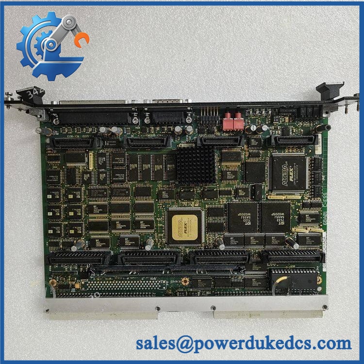
GE DS200DSPCH1ADA
🚨 Global Compliance & Industry Certifications
The DS200DSPCH1ADA is legacy industrial control hardware. Certification therefore needs to be evaluated against the complete Mark V/DS200 equipment and rack configuration, not the PCB alone.
- CE Mark: Verify the applicable Mark V equipment declaration for the specific installation and hardware revision.
- UL/cUL: Confirm the complete GE Mark V/ rack certification rather than treating the DSPC PCB as independently listed.
- ATEX / IECEx: Do not assume hazardous-area certification for the standalone DS200DSPCH1ADA.
- Marine approvals: DNV GL or other marine approval should not be assumed without project-specific documentation.
- EMC: The metal faceplate and mounting hardware provide a low-impedance path to earth ground for high-frequency interference control, which is part of the board’s intended installation arrangement.
- Electrical safety: The GE replacement procedure requires complete power removal and verification that no voltage remains before touching the board or connected circuits.
- Country of Origin: Establish from manufacturing traceability for the actual unit.
- HS Tariff Classification: Confirm the final code with the destination-country customs broker.
The board’s electrical and EMC characteristics depend partly on the VME rack, faceplate grounding, connector arrangement, and cabinet installation. Replacing the PCB without preserving those mechanical and grounding interfaces can compromise the intended installation conditions.
Verify specific lot certifications with OEM.
🚨 Long-Term Storage & Asset Preservation Guide
Keep the in an ESD shielding bag with the VME edge/interface protected. GE’s own DSPC maintenance instructions classify the board as static-sensitive and require anti-static storage and a grounding strap during handling.
Preserve the EEPROM and removable SIMM flash memory with the board whenever possible. During replacement, GE specifically notes that application information may need to be loaded into the new EEPROM/SIMM or the original devices transferred to the replacement board. This is a major spare-stock consideration for a legacy controller.
Maintain a dry, condensation-free warehouse. A practical long-term target below approximately 60% RH reduces connector oxidation and contamination risk, particularly around the VME connector and daughterboard sockets.
Before issue, inspect the card edge, six LEDs, recessed reset/boot pushbuttons, SIMM retaining clips, EEPROM socket, and all four daughterboard interfaces. Do not repeatedly remove the SIMM merely to inspect it; mechanical cycling adds unnecessary connector stress.
Physical Installation Prerequisites
Install the in the designated /Mark V VME rack position. The DSPC plugs into one VME slot but can occupy approximately two slots of physical space when daughterboards are installed, so adjacent-card clearance must be checked against the actual configuration.
Align the P1 and P2 DIN C96 connectors carefully with the VME backplane. Use the rack release tabs as designed; do not push against the PCB or connector bodies to force seating. GE’s replacement procedure also requires the faceplate hardware to be secured after the board is inserted.
Preserve daughterboard positions exactly. The four positions are electrically assignable during project configuration, but GE states that once assigned they are not interchangeable. Transfer each daughterboard into the same numbered position during replacement.
Maintain the faceplate-to-rack grounding path. The metal faceplate and mounting hardware are part of the high-frequency interference-control arrangement, so loose mounting screws are not merely a mechanical issue.
No universal 50 mm clearance should replace the actual VME rack design. Follow the original GE cabinet arrangement and preserve airflow around the processor board and its daughterboards.
Do not remove, insert, or reconnect the DSPC while power is applied. GE explicitly directs technicians to remove power, verify zero voltage, and discharge the equipment before board service.
Buyer’s FAQ — Logistics & Compliance Focus
Q: What HS Tariff Code should be used for ?
A: This is a specialized digital signal processor control board, but the final Harmonized System classification depends on the importing country’s tariff schedule and customs interpretation. Have the importer or customs broker confirm the final code before the commercial invoice is issued.
Q: Does the export location establish Country of Origin?
A: No. COO should be supported by manufacturing or traceability documentation for the actual . One supplier record identifies U.S. origin, but that information should not replace unit- or lot-level documentation.
Q: Does the include the latest firmware pre-loaded?
A: Do not assume it. The DSPC uses removable SIMM flash for program and FPGA configuration and socketed EEPROM for application configuration. GE’s replacement procedure specifically allows the original EEPROM/SIMM to be transferred to a new board when required, so the replacement hardware and software baseline must be reconciled before startup.
Q: How should shipping insurance and physical handling be managed?
A: Insure the board for its documented commercial replacement value and photograph the full part number, VME connectors, SIMM, EEPROM area, daughterboard positions, and faceplate before dispatch. Use ESD shielding, rigid protection for the connector edge, moisture control, and internal cushioning; supplier weight records vary, so the actual packed measurement should control the freight document.











 Start Chat


