

Description
- Model: GE DS200KLDBG1ABC
- Brand: GE / General Electric
- Series: Mark V DS200 / Speedtronic
- Part Type: Key/LED/Display Board
- Functional Acronym: KLDB
- Core Function: Provides local numerical and status indication for the Mark V control system through seven 16-segment LED displays and associated discrete indicator circuitry.
- Key Specs: 7 × 16-segment LED displays, 2 jumper switches, multiple indicator LEDs, 2 vertical pin connectors, normal PCB coating, Group 1 assembly, and three documented revision fields.
Product Introduction
When a legacy Mark V panel loses its local display, the control system may continue operating while operators lose direct access to important status and numerical information. The GE DS200KLDBG1ABC is identified as a Key/LED/Display Board for the Mark V series, providing the physical display and indication interface used by the turbine-control cabinet.
The board has a relatively large rectangular PCB format with seven 16-segment LED displays, arranged as two groups of three with a seventh display below the second group. Additional discrete LEDs, integrated circuits, resistor networks, capacitors, diodes, two jumper switches, and two vertical pin connectors are present. The exact Mark V cabinet position and connector assignment should be verified against the original system drawing before replacement (especially where field modifications have accumulated over time).
Core Technical Specifications
| Parameter | Value |
|---|---|
| Manufacturer | GE / General Electric |
| Catalog Number | DS200KLDBG1ABC |
| Product Family | Mark V DS200 |
| Functional Acronym | KLDB |
| Hardware Type | Key/LED/Display Board |
| Primary Function | Local numerical and status display |
| LED Displays | 7 |
| Display Technology | 16-segment LED |
| Discrete Indicator LEDs | 32 reported on the board |
| Jumper Switches | 2 |
| Vertical Pin Connectors | 2 |
| Integrated Circuits | Multiple |
| FPGA Devices | Multiple reported |
| Resistor Networks | Multiple |
| PCB Coating | Normal Coating |
| Mark V Group | Group 1 |
| Assembly Type | Normal Assembly |
| Revision Quantity | 3 significant revision fields |
| Board Markings | C-ESS, 6BA01 reported |
| Mounting | PCB screw/standoff mounting through drilled holes |
| Processor | Not applicable as a dedicated CPU board |
| User Memory | No user-memory specification established |
| Standalone Firmware | No independent field-firmware package established |
| Input Voltage | Exact board-level rating not verified |
| Power Consumption | Exact board-level rating not verified |
| Heat Dissipation | Exact board-level rating not verified |
| Reported Dimensions | Approximately 330 × 102 × 48 mm in a secondary source |
| Reported Weight | Approximately 0.54 kg in a secondary source |
| Estimated Shipping Weight | Approximately 1.0–1.5 kg with ESD and protective packaging |
| Lifecycle | Legacy / Obsolete |
The board construction, seven 16-segment displays, 32 discrete light components, two jumper switches, two vertical connectors, normal coating, Group 1 designation, and revision structure are documented in specialist Mark V parts records.
The 330 × 102 × 48 mm dimensions and 0.54 kg weight come from a secondary product listing and should be treated as logistics references rather than OEM-certified dimensions. Another supplier record gives different package dimensions and weight, reinforcing the need to measure the actual shipment before freight booking.
Application Scenarios & Pain Points
Micro-case — operator display failure: A Mark V turbine cabinet remains powered, yet the local numerical display becomes blank or partially unreadable. If the controller and field functions remain healthy, the KLDB can be isolated as a display-interface fault rather than replacing the main control electronics.
In turbine control environments, the seven 16-segment displays provide direct local indication without requiring an external workstation. This is particularly useful during commissioning and maintenance when the operator needs immediate visibility at the cabinet.
For legacy EX2000 and Mark V installations, the board provides a dedicated visual interface inside the control enclosure. It should not be confused with an HMI terminal or an independent controller; the board is an internal Mark V PCB.
When display segments fail individually, the troubleshooting path should distinguish between the LED display itself, its driver circuitry, connector contacts, and the upstream signal source. A partially operating display does not automatically indicate a failed board.
At 50°C+ cabinet temperatures, inspect the display drivers, capacitors, resistor networks, and connector solder joints for thermal aging. The publicly available exact-part documentation does not establish a reliable continuous operating-temperature limit, so the Mark V cabinet specification should govern.
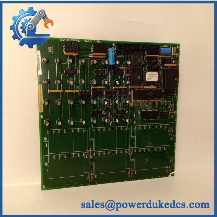
GE DS200KLDBG1ABC
🚨 Common Error Codes & Diagnostic Symptoms
No authoritative GE service document located for DS200KLDBG1ABC establishes a universal numerical fault-code table. The following are hardware symptoms intended for replacement troubleshooting.
Symptom/Code: All seven displays remain dark → Diagnosis: Possible loss of board supply, connector/interface failure, display-driver fault, or upstream control-data loss → Action: Verify cabinet power and connectors first, then substitute a known-good KLDB when the failure follows the board.
Symptom/Code: One or more display segments remain permanently lit or fail to illuminate → Diagnosis: Possible failed LED segment, display-driver component, solder connection, or associated logic circuit → Action: Compare the affected display with a known-good board and replace the KLDB if the board-level fault is confirmed.
Symptom/Code: Display flickers or resets intermittently during cabinet vibration → Diagnosis: Possible connector contact degradation, cracked solder joint, or unstable local power connection → Action: Inspect the two vertical pin interfaces and solder joints, then replace the board when mechanical intervention does not resolve the fault.
🚨 Cross-Reference & Lifecycle Migration
Exact Part Identity
The correct identification is:
GE DS200KLDBG1ABC — Key/LED/Display Board — KLDB
This is a Mark V DS200 display PCB rather than a CPU, analog-input card, or general-purpose I/O module.
Related Revision and Assembly References
A specialist Mark V parts record identifies three significant revision fields within the full DS200KLDBG1ABC number and notes that the first two are functional revisions, while the third is an artwork revision. The source also indicates that the first two functional revisions have backward-compatibility significance, while artwork revision changes should still be checked against the actual application.
Do not remove the final ABC suffix from purchasing records.
A related GE assembly, DS215KLDBG1AZZ03A, combines the display board with a DS200DSPAG1AAC assembly. That is a different higher-level assembly and should not be treated as the same standalone PCB.
Firmware Requirement
The is a display/interface board and does not use the same field-firmware process as a Mark V main processor or modern controller.
No reliable independent firmware-flashing procedure was established for the KLDB itself. If a replacement is installed, compatibility should instead be checked through the board revision, connectors, host controller, display interface, and Mark V system configuration.
Lifecycle Status
Lifecycle: Legacy / Obsolete.
Specialist parts records identify the board as no longer sold by GE and available mainly through legacy replacement and repair channels.
For critical turbine assets, stock should be tracked by complete catalog number and revision, with a tested spare retained where loss of local indication would materially affect maintenance or operation.
Field Engineer’s Tech Notes
First warning: photograph both jumper settings before removal. The KLDB has two jumper switches, and their positions should be copied exactly to the replacement unless the approved Mark V documentation specifies a change
Second warning: do not diagnose a dark display board by looking only at the LEDs. The board’s display system depends on upstream control signals and connector interfaces. Check the mating connectors, supply path, and host controller output before declaring the seven display assemblies defective (this is especially important when only one display section is affected).
Use an ESD wrist strap and an ESD-safe work surface whenever the PCB is outside the cabinet.
Strict QA & Testing SOP
1. Inbound identity verification
Confirm , functional acronym KLDB, and the complete revision suffix. Record all board markings, including C-ESS and 6BA01 where present.
2. Physical inspection
Inspect the PCB for cracked display bodies, damaged connector headers, corrosion, contamination, lifted components, broken mounting holes, and evidence of previous repair.
3. Display inspection
Visually inspect all seven 16-segment LED displays for cracked housings, dark segments, discoloration, or inconsistent brightness.
4. Jumper verification
Photograph both jumper positions and compare them with the customer’s original board.
5. Connector inspection
Check both vertical pin connectors for bent pins, oxidation, cracked housings, and loose solder joints.
6. Pre-power electrical check
Perform controlled continuity and resistance measurements on applicable supply and ground paths according to the Mark V maintenance procedure. Do not use undocumented board-level voltage figures as test limits.
7. Controlled power-up
Install the board in a compatible Mark V test assembly and apply the confirmed system supply. Observe startup behavior across all display positions.
8. Display-function test
Exercise the available numerical display functions and verify every segment of all seven displays. Test the associated discrete indicators where the test fixture exposes them.
9. Interface test
Verify data transfer between the display board and the host Mark V controller. Check for stable display updates during changes in the supplied test data.
10. Intermittent-fault test
Where safe and appropriate, perform controlled thermal and mechanical observation to identify unstable connectors or solder joints without stressing the PCB beyond its approved environmental limits.
11. Extended run
Operate the board under representative conditions and monitor display stability, brightness, connector integrity, and abnormal heating.
12. Final preservation
Place the approved board in ESD shielding packaging, protect both connectors and display surfaces from impact, and attach the inspection record.
Test videos are available when live functional testing is performed and visual evidence is required for procurement approval.
Buyer’s FAQ
Is a Mark V CPU board?
No. It is identified as a Key/LED/Display Board, with functional acronym KLDB. Its principal role is local numerical and status indication within the Mark V architecture.
How many displays are on the board?
The documented assembly contains seven 16-segment LED displays. In addition, the board has a separate field of approximately 32 discrete light components used for status indication.
Can the board be hot-swapped?
Do not assume energized removal is permitted. The KLDB is installed inside a turbine-control cabinet and interfaces with the host control system. De-energize the applicable equipment and follow the approved Mark V maintenance and electrical-isolation procedure before removal.
How do I verify New Original authenticity and warranty?
Request photographs of the actual , including the complete GE identification, KLDB marking, revision information, seven displays, two jumper switches, two vertical connectors, and packaging.
The purchase document should state New Original, New Surplus, refurbished, or repaired condition, together with the functional-test scope and warranty period.
For long-term asset control, retain + KLDB + full ABC revision + board markings + jumper configuration + host Mark V reference + COO + QC report + packaging condition as one controlled spare record.











 Start Chat


