

Description
-
- Model: DS200PCCAG1ABB
- Brand: GE
- Series: Mark V / DS200
- Product Type: PCCA Power Connect Card
- Functional Acronym: PCCA
- Primary Function: Interfaces drive control circuitry with the SCR power bridge in compatible DC drive assemblies.
- Drive Group: G1
- Drive Type: Regenerative
- Armature Voltage Scaling: 240–630 VDC
- Configurable Jumpers: JP1, JP2, WP3, WP4
- Instruction Manual: GEI-100161
- Approx. Board Weight: 1 lb
- Typical Application: GE Mark V/DC2000 drive systems and associated industrial drive assemblies.
Product Introduction
The GE DS200PCCAG1ABB PCCA Power Connect Card is a hardware interface board used within compatible GE Mark V/DC2000 drive architectures. Its role is between the drive control circuitry and the SCR power bridge, where the board supports gate-drive signal transmission and associated snubber and voltage-feedback functions. The G1 designation identifies this version as part of the regenerative PCCA group, with a listed 240–630 VDC armature-voltage range.
For maintenance teams supporting older turbine-control and DC-drive installations, the exact suffix matters. DS200PCCAG1ABB is not simply a generic PCCA reference; it represents a specific revision level within the G1 family. Substituting another DS200PCCA variant without checking the drive frame, control architecture, jumper arrangement, and application data can create commissioning or protection issues. The applicable PCCA documentation is identified as GEI-100161.
Core Technical Specifications
Specification Details Manufacturer GE Part Number DS200PCCAG1ABB Product Series Mark V / DS200 Functional Description PCCA Power Connect Card Functional Acronym PCCA Board Group G1 Drive Classification Regenerative Armature Voltage Scaling 240–630 VDC Interface Role Drive control circuitry to SCR power bridge Configurable Jumpers JP1, JP2, WP3, WP4 JP1 Function DC armature-voltage range selection JP2 Function Used with JP1 for DC armature-voltage range selection WP3 Function Snubber and voltage-feedback connection configuration WP4 Function Snubber and voltage-feedback connection configuration Instruction Manual GEI-100161 Board Weight Approximately 1 lb Shipping Dimensions Listed by Supplier 18 × 12 × 12 in. Firmware No standalone firmware function identified for the PCCA board Installation Dependency Drive architecture, power bridge, frame, and jumper configuration dependent The 240–630 VDC value refers to the listed armature-voltage scaling for the G1 board group. The exact permissible system voltage, drive configuration, and associated AC-side conditions should be confirmed against the installed drive documentation rather than inferred from the PCB part number alone.
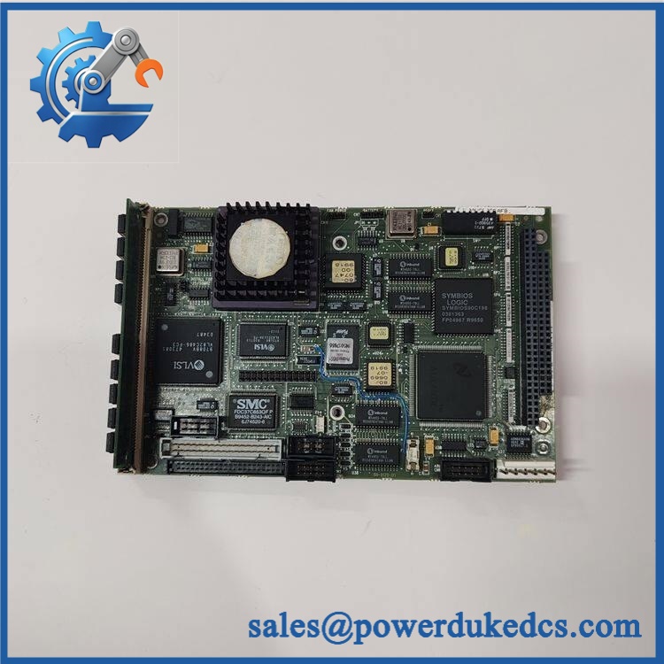
GE DS200PCCAG1ABB
Application Scenarios & Maintenance Considerations
GE DC2000 Regenerative Drive Maintenance
When a legacy DC drive reaches a board-level failure, the DS200PCCAG1ABB can become a critical replacement item because the PCCA sits directly within the power-interface path. Delays are often less about the PCB itself than about identifying the correct revision before removing the failed board.
Technical consideration: compare the complete part number, board artwork/revision markings, connector arrangement, and jumper settings before installation.
SCR Power Bridge Interface
The PCCA functions as an interface between the drive control circuitry and the SCR bridge. Its circuitry is associated with gate-drive pulse transmission, snubber functions, and voltage-feedback connections.
A failed PCCA may therefore present as a drive-level power-conversion problem rather than an obviously isolated PCB fault.
Regenerative Drive Applications
The G1 group is identified as regenerative. Other PCCA groups exist, including non-regenerative configurations, so replacing a G1 board with another group based only on physical similarity is not a safe assumption.
Emergency Spare-Parts Planning
For facilities operating legacy GE drive equipment, holding a tested spare can reduce the time between board failure and controlled restart. A practical inventory record should include the complete DS200PCCAG1ABB number, revision information, installed drive model, frame information, and the documented jumper configuration.
Obsolescence and TCO
Mark V/DC2000 hardware belongs to a legacy control environment, making exact-revision sourcing increasingly important. Inventory decisions should account for lead time, available tested stock, remaining installed-base demand, and the cost of an extended drive outage rather than PCB purchase price alone. Current specialist inventories continue to list as a replacement/stock item, but availability can vary by condition and lot.
Common Error Symptoms & Diagnostic Direction
Symptom: SCR Firing or Gate-Drive Abnormality
Code: No standalone PCCA fault-code system
Diagnosis: Inspect the PCCA interface, associated gate-drive wiring, pulse-transformer path, connectors, and power-bridge condition.
Action: Confirm connector integrity and the board’s jumper configuration before replacing the PCB.Symptom: Incorrect Armature-Voltage Feedback
Code: Drive-level voltage or feedback alarm
Diagnosis: Verify JP1/JP2 settings against the installed drive’s DC armature-voltage range and application documentation.
Action: Do not copy jumper positions from another PCCA revision without checking the applicable manual.Symptom: Snubber / Power-Bridge Related Fault
Code: Drive-level power-stage fault
Diagnosis: Inspect WP3/WP4 configuration and the associated snubber and voltage-feedback connections.
Action: Isolate and discharge the drive power section before any physical inspection or board replacement.The PCCA itself is a hardware interface card, so diagnostic information is normally obtained from the surrounding drive/control system rather than from a dedicated onboard fault display.
Cross-Reference & Lifecycle Migration
The belongs to the G1 PCCA family. Related PCCA configurations include other G1 revisions and different group numbers such as G2, G7, and G8. These variants can differ by regenerative status, snubber arrangement, power-supply relationship, and system application.
For replacement planning, treat the following as separate verification items:
- Complete part number and all suffix characters
- Functional and artwork revisions
- Regenerative vs. non-regenerative configuration
- Drive frame and power architecture
- Installed jumper settings
- SCR bridge and associated power components
- Existing board documentation and application drawings
A same-family board should not automatically be treated as a drop-in replacement. For a legacy installation, preserving one verified spare with the application’s recorded jumper settings can be more useful than storing several unverified PCCA variants.
Field Engineer’s Tech Notes
1. Record jumper positions before removing the failed card.
JP1 and JP2 are associated with DC armature-voltage range selection, while WP3 and WP4 relate to snubber and voltage-feedback configuration. A visually identical replacement can still require application-specific configuration.2. Treat the board as part of a high-energy drive assembly.
Power must be isolated, locked out, and discharged according to the drive’s service procedure before touching the PCCA, associated connectors, or SCR bridge. Do not use a continuity check or visual inspection as a substitute for proper drive isolation.Strict QA & Testing SOP
For a replacement , incoming inspection should cover:
Part-number verification
Confirm the complete identifier and compare board markings with the purchase specification.Revision verification
Record all visible functional/artwork revision markings. Avoid mixing revision data between visually similar PCCA boards.Physical inspection
Check the PCB, connectors, jumper hardware, transformers, capacitors, solder joints, and board surface for corrosion, impact damage, contamination, or signs of overheating.Configuration inspection
Document JP1, JP2, WP3, and WP4 before shipment when the board is supplied as a tested spare. The recorded settings should correspond to the intended drive application.Electrical inspection
Where test equipment and an appropriate drive test rig are available, verify the relevant interface and power-stage behavior under controlled conditions. High-energy SCR drive testing should be performed only with equipment designed for the applicable voltage and current range.Packaging and ESD protection
Use ESD-safe packaging with mechanical protection around connectors and board edges. The board should remain protected from moisture, conductive contamination, and shock during international transportation.QC Documentation
A professional supply package can include serial/part-number records, visual inspection results, test status, packing photos, and available test videos.Buyer’s FAQ
Is a regenerative board?
Yes. The G1 designation identifies the as a regenerative PCCA configuration, with the listed 240–630 VDC armature-voltage scaling.
Does use firmware?
The PCCA is a hardware interface board rather than a standalone programmable controller, so firmware flashing is not normally treated as a board-level maintenance task. The important configuration variables are hardware-related, including jumper settings and system application parameters.
What manual applies to this part?
The listed instruction manual is GEI-100161, covering the PCCA Power Connect Card family.
What should be confirmed before purchasing?
Provide the complete part number and, where possible, the installed drive model, frame information, board revision markings, and existing jumper configuration. For a replacement project, these details reduce the risk of receiving a physically similar but functionally different PCCA variant.
What is the approximate shipping weight?
One current specialist listing gives the board weight as approximately 1 lb and lists shipping dimensions of 18 × 12 × 12 inches. Actual packed weight depends on the protective packaging used for shipment.
Is suitable for a new system design?
This part is primarily relevant to maintaining an existing legacy GE Mark V/DC2000 installation. For a new system, the appropriate approach depends on the required drive architecture, control platform, power rating, and lifecycle requirements rather than selecting a legacy PCB as a standalone component.











 Start Chat


