

Description
- Model & Brand: GE DS200RTBAG2AFB, General Electric
- Series: Mark V DS200 / Speedtronic
- Functional Acronym: RTBA
- Part Type: Relay Terminal Board
- Relay Count: 10 relays, designated K20 through K29.
- Physical dimensions: Exact OEM dimensional drawing for the DS200RTBAG2AFB was not located in the available technical record. Use the actual board and packed carton measurements for freight documentation.
- Estimated unit weight: Approximately 0.8–1.2 kg, logistics estimate only.
- Estimated shipping weight: Approximately 1.2–1.8 kg with ESD protection, cushioning, and carton.
- What’s in the Box: DS200RTBAG2AFB board assembly and protective packaging when supplied as unused stock. Do not assume external relays, terminal wiring, cables, mounting hardware, or manuals are included.
- Electrical identity: The board uses a 24 VDC control-power supply and contains seven DPDT relays plus three 4PDT relays.
Product Introduction
Within the GE Mark V control architecture, the DS200RTBAG2AFB provides the relay interface between control-system logic and external circuits. The board is identified as an RTBA Relay Terminal Board, with ten relays arranged from K20 to K29. This makes it a field-interface component rather than a processor or general-purpose I/O controller.
The relay population is important during replacement. K20–K26 are seven DPDT relays with two Form-C contacts, each rated at 10 A according to the available parts documentation; K27–K29 are three 4PDT relays with four Form-C contacts rated at 1 A each. The coils are specified as 110 VDC, while the board’s control-power supply is listed as 24 VDC. A 130 VAC MOV is provided for relay protection.
Core Technical Specifications
| Parameter | Value |
|---|---|
| Manufacturer | GE / General Electric |
| Catalog Number | DS200RTBAG2AFB |
| Product Family | Mark V DS200 |
| Functional Acronym | RTBA |
| Hardware Type | Relay Terminal Board |
| Primary Function | Relay output and field-terminal interface |
| Control Power | 24 VDC |
| Relay Positions | K20–K29 |
| Total Relays | 10 |
| K20–K26 Relay Type | DPDT |
| K20–K26 Contact Configuration | 2 × Form-C contacts per relay |
| K20–K26 Contact Rating | 10 A per contact |
| K27–K29 Relay Type | 4PDT |
| K27–K29 Contact Configuration | 4 × Form-C contacts per relay |
| K27–K29 Contact Rating | 1 A per contact |
| Relay Coil | 110 VDC internal coil |
| MOV Protection | 130 VAC MOV |
| Main Connector | 16-pin RPL |
| Secondary Connector | 2-pin OPTPL |
| Terminal Points | 52 |
| RPL Continuously Connected Pins | 1, 3, 5, 7, 9, 11, 13, 15 |
| Additional Diagnostic Labels | X2 / CFX1 on OPTPL interface |
| PCB Revision Structure | Three significant revisions in the full DS200 number |
| Mark V Group | G2 |
| Board Coating | Revision-dependent; exact coating should be checked on physical unit |
| Processor | None as a dedicated CPU |
| User Memory | None |
| Standalone Firmware | None documented |
| Heat Dissipation | Exact OEM value not verified |
| Operating Temperature | Approximately 0–60°C in secondary records |
| Board Dimensions | Exact OEM drawing not verified |
| Unit Weight | Approx. 0.8–1.2 kg, estimated |
| Shipping Weight | Approx. 1.2–1.8 kg, estimated |
| Lifecycle | Legacy / Obsolete |
The relay arrangement, control power, connector designations, terminal count, coil voltage, and MOV protection are documented in specialist DS200RTBAG2AFB records.
A key engineering point concerns the contact ratings. 10 A applies to the specified DPDT relay contacts and not to every relay on the board. K27–K29 use 1 A contacts, so the load circuit must be matched to the individual relay position.
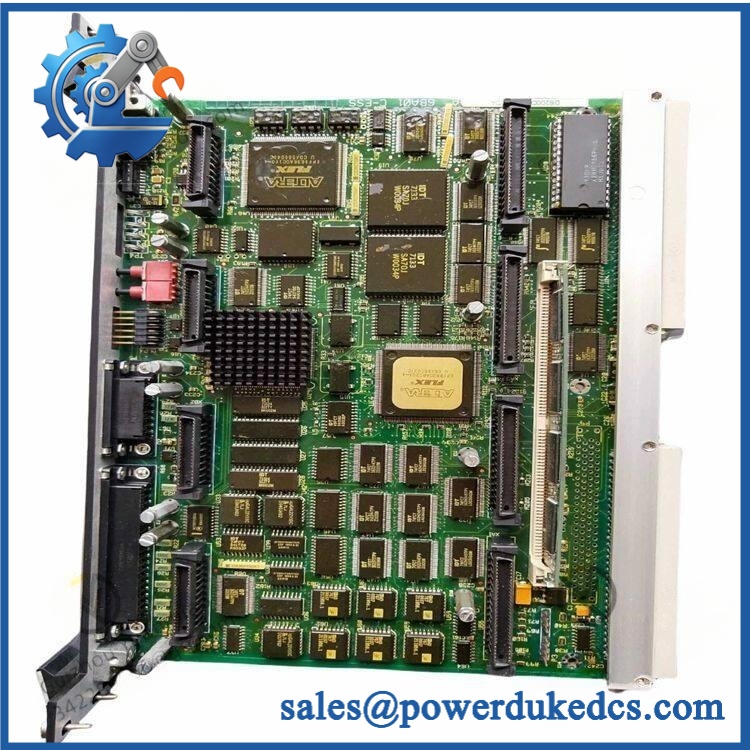
GE DS200RTBAG2AFB
Application Scenarios & Pain Points
Micro-case — failed turbine control relay: A Mark V digital-output command reaches the relay interface, but an external solenoid does not actuate. Once the upstream control signal and field wiring are confirmed, the corresponding RTBA relay and terminal path become the next diagnostic targets.
For turbine and generator control cabinets, the board provides ten additional relay functions, with the LAN I/O terminal and remote user able to drive the relays according to the installed architecture.
Where high-current AC or DC circuits are switched, K20 through K26 require particular attention because their documented contact rating differs from the K27–K29 group. A board can therefore be mechanically identical while the wrong relay position is electrically unsuitable for the field load.
In legacy Mark V cabinets, the 16-pin RPL and 2-pin OPTPL connectors carry specific signals between the relay board and associated terminal/control boards. The published documentation identifies 52 terminal points, making point-by-point wiring verification worthwhile before removal.
At 50°C+ ambient temperatures, inspect relay housings, terminal connections, solder joints, and MOV components carefully. Secondary specifications place the board’s operating range around 0–60°C, so cabinet thermal conditions should be checked against the actual Mark V system specification.
🚨 Common Error Codes & Diagnostic Symptoms
No authoritative GE source located for this exact board establishes a universal numerical RTBA fault-code system. Troubleshooting should therefore focus on relay operation, control power, field continuity, and connector signals.
Symptom/Code: Command present, relay contact remains open → Diagnosis: Possible failed relay coil, contact mechanism, control-power problem, or upstream drive signal → Action: Verify the 24 VDC control supply and relay command, then test contact continuity and replace the RTBA when the failure follows the board.
Symptom/Code: Relay contact remains closed after command removal → Diagnosis: Possible welded or mechanically stuck contact, particularly after excessive load or inadequate suppression on an inductive circuit → Action: Isolate the field circuit and replace the affected relay or board according to the approved maintenance procedure.
Symptom/Code: Multiple relay channels fail simultaneously → Diagnosis: A common control-power, connector, or interface problem is more likely than simultaneous mechanical failure of several relays → Action: Check the 24 VDC supply, RPL/OPTPL interfaces, and associated terminal boards before replacing the RTBA.
🚨 Cross-Reference & Lifecycle Migration
Exact Part Identity
GE = RTBA Relay Terminal Board, Mark V DS200, Group G2.
The underlying base board is identified as DS200RTBAG2, with the AFB revision tail identifying later functional/artwork changes. The exact suffix should be retained in the asset database and purchase order.
Related Part Numbers
GE’s Mark V inventory contains numerous RTBA variants, including:
- DS200RTBAG1A
- DS200RTBAG1ABB
- DS200RTBAG1AFB
- DS200RTBAG2A
- DS200RTBAG2AGC
- DS200RTBAG2AHC
- DS200RTBAG3
- DS200RTBAG4A
These are related relay-terminal-board products, not automatically interchangeable replacements.
The exact G2 / AFB configuration should be matched against the existing terminal wiring and relay arrangement.
Connector and Terminal Compatibility
The uses:
- RPL — 16-pin connector
- OPTPL — 2-pin connector
- 52 field terminal points
The RPL connector has eight consistently connected odd-numbered pins: 1, 3, 5, 7, 9, 11, 13, and 15. The remaining interface details depend on the Mark V application and board configuration.
Firmware Requirement
No firmware flashing applies to the itself. It is a relay terminal/interface board without a dedicated user-programmed CPU.
Replacement concerns are hardware-based: relay type, coil circuit, contact rating, connector wiring, terminal assignment, MOV protection, and host Mark V configuration.
Lifecycle Status
Lifecycle: Legacy / Obsolete.
The Mark V DS200 generation is an established legacy control platform, with current stock primarily supplied through specialist spare-parts, repair, and surplus channels. GE parts records continue to identify the RTBA family for maintenance purposes.
For critical turbine equipment, inventory should be controlled by complete catalog number and revision, with the relay population and terminal configuration documented.
Field Engineer’s Tech Notes
First warning: never use the 10 A rating for K27–K29. Those three relays are the 4PDT group with 1 A contact ratings. Before commissioning, identify the exact relay position and load type from the cabinet schematic.
Second warning: do not disconnect the RPL connector without documenting the existing wiring. The 16-pin interface carries relay-related signals, and not every pin is continuously connected. Photograph the connector and terminal arrangement before removal (this is especially valuable when the cabinet contains field modifications).
Also check the CPH and CPN control-power stab connections reported on the RTBA assembly. A poor connection in this area can create multiple relay symptoms at once.
Strict QA & Testing SOP
1. Inbound identity verification
Confirm , RTBA designation, G2 group, and the complete revision suffix. Photograph all board markings and labels.
2. Relay inventory check
Verify relay positions K20–K29. Confirm seven DPDT relays at K20–K26 and three 4PDT relays at K27–K29.
3. Physical inspection
Inspect relay housings, terminal blocks, connector bodies, jumper areas, MOV components, solder joints, and PCB surfaces for cracking, corrosion, overheating, or previous repair.
4. Connector inspection
Check the 16-pin RPL and 2-pin OPTPL connectors for bent contacts, corrosion, loose solder joints, and mechanical damage.
5. Terminal verification
Confirm all 52 terminal points are physically intact and correctly identified.
6. Control-power test
Verify the board’s required 24 VDC control-power arrangement before energization. Check CPH/CPN connections where fitted.
7. Relay coil test
Check the relay coils for continuity and abnormal resistance using the applicable GE maintenance procedure. The documented relay coil is 110 VDC, so do not confuse coil voltage with the board’s 24 VDC control-power specification.
8. Contact test
Exercise K20 through K29 individually. Verify pickup, dropout, normally open/normally closed contact behavior, and contact continuity.
9. Load simulation
Use controlled resistive and suitable inductive loads within the rating of the specific relay being tested. K20–K26 and K27–K29 require different acceptance criteria.
10. Interface test
Verify the RPL and OPTPL signal paths against the applicable Mark V terminal-board configuration.
11. MOV/protection inspection
Inspect the 130 VAC MOV protection devices for cracking, discoloration, or evidence of surge exposure.
12. Extended observation
Cycle representative relay outputs repeatedly while monitoring for contact bounce, delayed dropout, abnormal coil heating, or intermittent operation.
13. Final preservation
Place the approved board in ESD-safe packaging, protect the relay and terminal areas from impact, and attach the complete QC record.
Test videos are available when live-rig testing is performed and visual evidence is required for procurement approval.
Buyer’s FAQ
Is a digital output card?
No. It is a Relay Terminal Board. The board provides relay contacts and terminal interfaces for signals originating from the Mark V control system.
Are all ten relays rated at 10 A?
No. K20–K26 use DPDT relays with two Form-C contacts rated at 10 A each in the available technical record. K27–K29 use 4PDT relays with four Form-C contacts rated at 1 A each.
Can the board be hot-swapped?
Do not assume live removal is permitted. The board interfaces with control power and external relay circuits, and some connected circuits can involve hazardous voltage. De-energize and isolate the relevant equipment according to the Mark V maintenance procedure and site lockout/tagout requirements before removal.
How do I verify New Original authenticity and warranty?
Request photographs of the actual , including the GE identification label, revision suffix, ten relay positions, RPL and OPTPL connectors, terminal points, and packaging.
The purchase documentation should state New Original, New Surplus, refurbished, or repaired condition, together with the functional-test scope and warranty period.
For a controlled Mark V spare, retain + RTBA + G2 revision + K20–K29 relay configuration + RPL/OPTPL identification + 52-terminal configuration + host-system reference + COO + QC record + packaging condition as the complete asset record.











 Start Chat


