

Description
- Brand: GE Fanuc
- Full Model Number: IC670ALG310
- System/Series Family: Genius Field Control Distributed I/O
- One-Sentence Core Function: Eight-channel isolated analog voltage-source output module providing configurable DC voltage signals to external control devices
- Top 3 Hardcore Specs: 8 isolated outputs; -10 to +10 VDC or 0 to +10 VDC; 14-bit resolution
- Stock Status: New Surplus / Fully Tested Refurbished — exact module revision and field-control hardware condition verified before shipment
Module 3: Commercial-Technical Deep Dive
When a DCS or drive loses an analog command signal, the problem can be isolated to one output module while the Genius Bus and remote station remain online. The GE Fanuc IC670ALG310 is an 8 Point Isolated Analog Voltage-Source Output Module for the GE Genius Field Control system. GE’s original GFK-1426 documentation specifies eight voltage outputs arranged as two isolated groups of four, with configurable scaling and both bipolar and unipolar operating ranges. The module generates output voltages from -10 VDC to +10 VDC with 14-bit resolution, making it suitable for proportional commands and reference signals where electrical isolation between output groups is required.
The signal-processing details matter during replacement. Each channel can use either a -10 to +10 V bipolar range or a 0 to +10 V unipolar range, with user-defined engineering scaling. GE also specifies an output overrange capability to approximately ±10.25 V, while a published product reference identifies a 5 kΩ minimum load and approximately 170 mA backplane current for the module. The output data is supplied by the Genius Bus host in engineering units and converted by the module’s DAC into the configured voltage signal. A replacement can therefore power up normally yet still command the wrong process value if the channel range or scaling parameters were not restored.
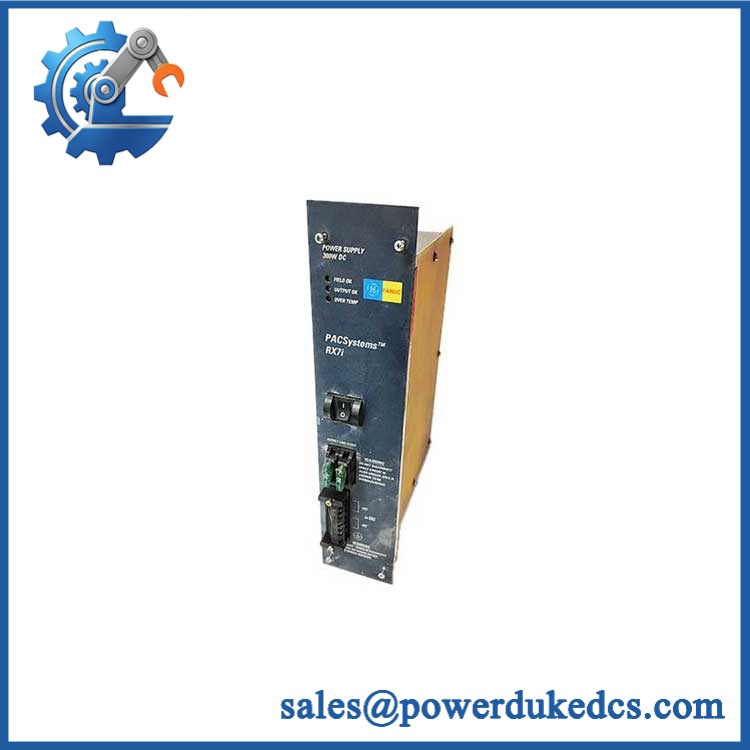
GE IC670ALG310
Module 4: Compatibility & Installation Traps
Migration/Compatibility
- Replacement status: Configuration-specific Genius Field Control analog-output module.
- Official identification: IC670ALG310, 8 Point Isolated Analog Voltage-Source Output Module.
- Output architecture: 8 outputs in two isolated groups of four.
- Output ranges: -10 to +10 VDC and 0 to +10 VDC, individually configurable.
- Resolution: 14-bit.
- Firmware requirement: No independent firmware flash is normally associated with the analog module. Preserve the Genius Bus configuration and output scaling parameters.
- Logic rewrite: Normally not required for a same-part-number replacement, but channel assignments, scaling, active/inactive status, and host reference mapping must be validated.
- BIU compatibility: GE documentation identifies IC670ALG310 as an intelligent Field Control module configured through a compatible Genius Bus Interface Unit; published references specify BIU revision 2.0 or later.
⚠️ Field Traps (Watch Out)
- Bipolar versus unipolar range: A channel configured for -10 to +10 V cannot be treated like a 0–10 V output simply because both use the same terminals. Verify the configured range for every active channel.
- Scaling mismatch: GE permits user-defined engineering-unit scaling. The voltage output may look electrically correct while representing the wrong process value if the scaling constants are incorrect.
- Two isolated groups: Channels are arranged as two isolated groups of four. Do not common the returns across groups unless the system wiring documentation explicitly permits it.
- External output supply: The output circuits require a separate field power source. Loss of that supply can produce an inactive output even when the Genius Bus and module electronics are healthy.
- Minimum load: The published field specification identifies a 5 kΩ minimum load. Confirm the receiving analog input impedance before commissioning.
- Terminal-base dependence: The module is installed on a Field Control I/O terminal block. Verify the exact terminal base and field wiring before accepting the replacement.
- ESD and power isolation: Remove applicable backplane and user power, then use grounded ESD handling before replacing the module.
Module 5: Quality Assurance SOP
Our pre-shipment inspection for a GE IC670ALG310 focuses on output accuracy, isolation, scaling, and Genius Bus communication:
- OEM anti-counterfeit visual inspection — verify GE Fanuc/Genius identification, complete IC670ALG310 part number, revision markings, PCB artwork, status LED, connector interfaces, and manufacturing labels.
- Revision capture — photograph the module label, front assembly, rear interface, and all secondary identification markings.
- Terminal-base verification — confirm the module is installed with the appropriate Field Control terminal assembly for the customer’s station.
- PCB inspection — check isolation components, connectors, solder joints, calibration circuitry, contamination, corrosion, and thermal discoloration.
- Backplane power verification — apply the required Field Control station power under controlled laboratory conditions and verify expected module initialization.
- External output-power verification — provide the separate field supply required by the output circuit and confirm stable voltage under no-load conditions.
- Power-on self-test (POST) — verify the status indicator shows normal operation and does not enter the documented fault-flashing condition.
- Eight-channel output test — command each analog output individually and measure the actual voltage with calibrated instrumentation.
- Bipolar-range verification — test representative points across the -10 to +10 VDC range and confirm correct polarity and scaling.
- Unipolar-range verification — configure representative channels for 0 to +10 VDC operation and verify the corresponding output response.
- Resolution and linearity check — apply multiple digital command values across the operating range and compare the measured voltage against the expected engineering-unit conversion.
- Overrange verification — where the approved test procedure permits, verify the documented overrange behavior without exceeding equipment limits. GE specifies output capability of approximately ±10.25 V.
- Isolation verification — test representative isolation between the two groups of four channels using an appropriately rated instrument and procedure.
- Load test — connect representative resistive loads and verify output stability while respecting the documented 5 kΩ minimum load condition.
- Genius Bus communication handshake verification — connect the module to a compatible BIU and confirm module recognition, configuration, and stable output-data exchange.
- Scaling/configuration test — verify representative channel scaling and active/inactive settings through the approved Field Control configuration procedure.
- Extended observation — monitor output drift, isolation behavior, communication stability, and module temperature during controlled continuous operation.
- Final QC record — document part number, revision, terminal assembly, output range per channel, measured voltages, scaling settings, isolation results, and photographs.
- Final ESD packaging — protect the module and field connectors against ESD, moisture, dust, and mechanical impact before shipment.
GE’s original documentation establishes the core acceptance criteria: 8 isolated voltage outputs, two groups of four, 14-bit resolution, -10 to +10 V and 0 to +10 V ranges, field calibration, FLASH-stored calibration data, and under/overrange diagnostics.
Module 6: CRO-Driven Buyer FAQ
1. Is GE obsolete?
Yes. Current industrial inventory references list as discontinued by the manufacturer, making verified installed-base stock particularly relevant for maintaining legacy Genius Field Control stations.
2. How many analog outputs does have?
It provides 8 isolated analog voltage outputs, arranged in two isolated groups of four.
3. What voltage ranges are supported?
Each channel supports -10 to +10 VDC bipolar operation or 0 to +10 VDC unipolar operation, with configurable engineering scaling.
4. What is the output resolution?
The provides 14-bit output resolution. GE also documents approximately ±10.25 V output overrange capability.
5. Does require a separate power supply?
Yes. GE’s documentation states that the analog output circuits require a separate source of power. The module also draws power from the station backplane. Verify both supplies before diagnosing an apparent output failure.
6. Can be hot-swapped?
Do not assume live replacement is permitted. The module interfaces with the Field Control station backplane and externally powered analog circuits. Remove the applicable backplane and field power, follow the GE Genius Field Control maintenance procedure, and apply the site’s LOTO requirements before replacement.
7. What warranty and technical support should I expect?
Warranty duration should be stated on the quotation for the exact physical module supplied. Technical support should cover part-number and revision verification, terminal-base compatibility, output-range and scaling checks, isolation testing, Genius Bus configuration, and documented pre-shipment QA results. It should not substitute for process-control engineering, analog-loop commissioning, or site electrical-safety validation.











 Start Chat


