

Description
- Brand: GE Fanuc
- Full Model Number: IC670CHS101
- System/Series Family: GE Field Control Distributed I/O
- One-Sentence Core Function: Barrier-style I/O terminal block providing field wiring, module mounting, and backplane communication connections for two Field Control I/O modules
- Top 3 Hardcore Specs: 37 terminals; up to 2 I/O modules; AWG #14 maximum wire size per terminal
- Stock Status: New surplus / fully tested refurbished
The GE IC670CHS101 is a Field Control I/O Terminal Block with barrier terminals. GE documentation specifies 37 terminals, with each terminal accommodating one or two wires up to AWG #14. The terminal block provides module mounting, field wiring, and the interconnection path between Field Control I/O modules and the Bus Interface Unit.
Module 3: Commercial-Technical Deep Dive
A damaged terminal base can force an entire distributed I/O position out of service even when the electronic I/O module itself is healthy. The GE IC670CHS101 is the mechanical and electrical termination platform used by the GE Field Control system, supporting two I/O module positions and providing the field terminals required by the installed modules. GE documentation identifies the barrier-terminal version as a 37-terminal assembly, while the terminal block also carries the cable connection used to extend communications to the next terminal block.
The installation details are where this part earns its maintenance value. Each terminal can accommodate one or two AWG #14 conductors, and the block mounts on a 35 mm × 7.5 mm DIN rail that forms part of the grounding system; the rail must be electrically conductive rather than painted. The IC670CHS101 also includes projecting alignment features that support hot insertion/removal when used with the correct I/O modules and Bus Interface Unit revision. That makes the exact terminal-block revision a functional consideration, not merely a mechanical one.
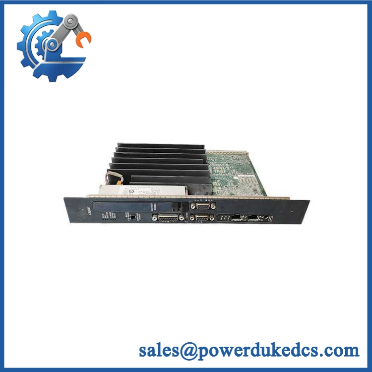
GE IC670CHS101
Module 4: Compatibility & Installation Traps
Migration/Compatibility
- Replacement type: GE Field Control I/O terminal block
- Model: IC670CHS101
- Terminal style: Barrier terminals
- Terminal count: 37
- Module capacity: 2 I/O modules
- Mounting: 35 mm × 7.5 mm DIN rail or panel mounting
- Firmware flash: Not applicable
- Logic rewrite: Not applicable
- Drop-in status: Generally suitable when replacing the same IC670CHS101 terminal block, subject to module revision, Bus Interface Unit revision, grounding arrangement, and existing field wiring
- Hot insertion/removal: Supported only under the documented hardware conditions: appropriate I/O modules, an applicable Bus Interface Unit revision, and a non-hazardous installation.
⚠️ Field Traps (Watch Out)
1. Hot insertion is conditional, not universal.
GE documentation specifies that the supports hot insertion/removal only when used with I/O modules carrying the required J-or-later suffix and an appropriate Bus Interface Unit. Older modules without the alignment feature do not receive the same hot-insertion protection.
2. Check the DIN rail grounding system.
The uses a metal grounding strip and must be installed on a grounded, conductive DIN rail. GE specifically warns against combining this terminal-block generation with incompatible earlier Field Control hardware because the grounding arrangement can reduce system noise immunity.
3. Do not mix CHS10x and CHS00x terminal blocks casually.
GE documentation recommends against mixing with IC670CHS001/002/003 within the same I/O station. The different generations use different alignment and grounding arrangements.
4. Terminal capacity is not the same as load rating.
The AWG #14 figure specifies conductor accommodation. It does not establish the current rating of every Field Control I/O module installed on the block. The electrical limits come from the specific I/O module and field circuit.
5. Preserve field wiring during terminal-block replacement.
Because the terminal block is the physical field-wiring interface, disconnecting it can create numerous wiring errors. Photograph each terminal position and mark all conductors before removal.
Module 5: Quality Assurance SOP
Each GE unit should pass a documented pre-shipment inspection sequence:
- OEM anti-counterfeit visual inspection: Verify GE Fanuc identification, catalog marking, barrier-terminal layout, mounting hardware, alignment features, and manufacturing markings.
- Exact part-number verification: Match the complete catalog number against the purchase order and installed Field Control BOM.
- Terminal-count verification: Confirm the documented 37-terminal barrier arrangement.
- Mechanical inspection: Check terminal barriers, screws, DIN-rail latch, panel-mounting feet, alignment tabs, cable connectors, keying slots, grounding point, and housing for cracks, corrosion, deformation, or damage.
- Terminal integrity inspection: Verify that every terminal clamps correctly and that no screws are stripped, seized, or mechanically damaged.
- Grounding inspection: Confirm the grounding strip is intact and verify compatibility with a conductive grounded DIN rail.
- Power-on self-test (POST): Not applicable to the passive terminal block. Functional testing is performed with the appropriate Bus Interface Unit and I/O modules installed.
- Module-interface verification: Install representative compatible Field Control I/O modules and verify correct mechanical seating, alignment, keying, and electrical contact.
- Backplane communication verification: With a compatible Bus Interface Unit and I/O modules, confirm stable station communication and correct module recognition.
- Hot-insertion verification: Where the test setup and applicable hardware permit, verify module insertion/removal behavior under the documented non-hazardous operating conditions.
- Final QC: Photograph the catalog marking and terminal layout, record compatibility and mechanical inspection results, and package the terminal block to protect terminals and alignment features from impact.
Module 6: CRO-Driven Buyer FAQ
1. What is GE ?
The is a GE Field Control I/O Terminal Block with barrier terminals. It provides field wiring, module mounting, and the interconnection path for Field Control distributed I/O. GE documentation specifies 37 terminals and support for the Field Control I/O module architecture.
2. How many I/O modules can accommodate?
The terminal block provides positions for two Field Control I/O modules. Each module position has its own terminal connections and communication interface to the station wiring architecture.
3. Can support hot insertion and removal?
Yes, but only under specific conditions. GE documentation states that the is designed for hot insertion/removal when paired with compatible I/O modules carrying the required alignment feature and an appropriate Bus Interface Unit. The procedure applies only in non-hazardous locations, and separate I/O module power must be switched off during the operation.
4. What wire size does accept?
Each barrier terminal can accommodate one or two wires up to AWG #14, approximately 2.1 mm² conductor cross-section. GE recommends suitable copper conductors and specifies terminal torque requirements in its installation documentation.
5. What warranty and technical support are provided?
Warranty duration should be stated on the quotation for the exact inventory condition supplied. Technical support should cover catalog-number verification, terminal compatibility, module alignment, DIN-rail grounding checks, inspection records, and Field Control station integration guidance. Field rewiring and energized maintenance remain the responsibility of qualified controls personnel.











 Start Chat


